APJ ABDUL KALAM TECHNOLOGICAL UNIVERSITY Previous Years Question Paper & Answer
Semester : SEMESTER 5
Subject : Digital Signal Processing
Year : 2019
Term : DECEMBER
Scheme : 2015 Full Time
Course Code : EC 301
Page:2
a)
b)
a)
b)
a)
b)
௦)
a)
b)
0)
a)
E192002 Pages:3
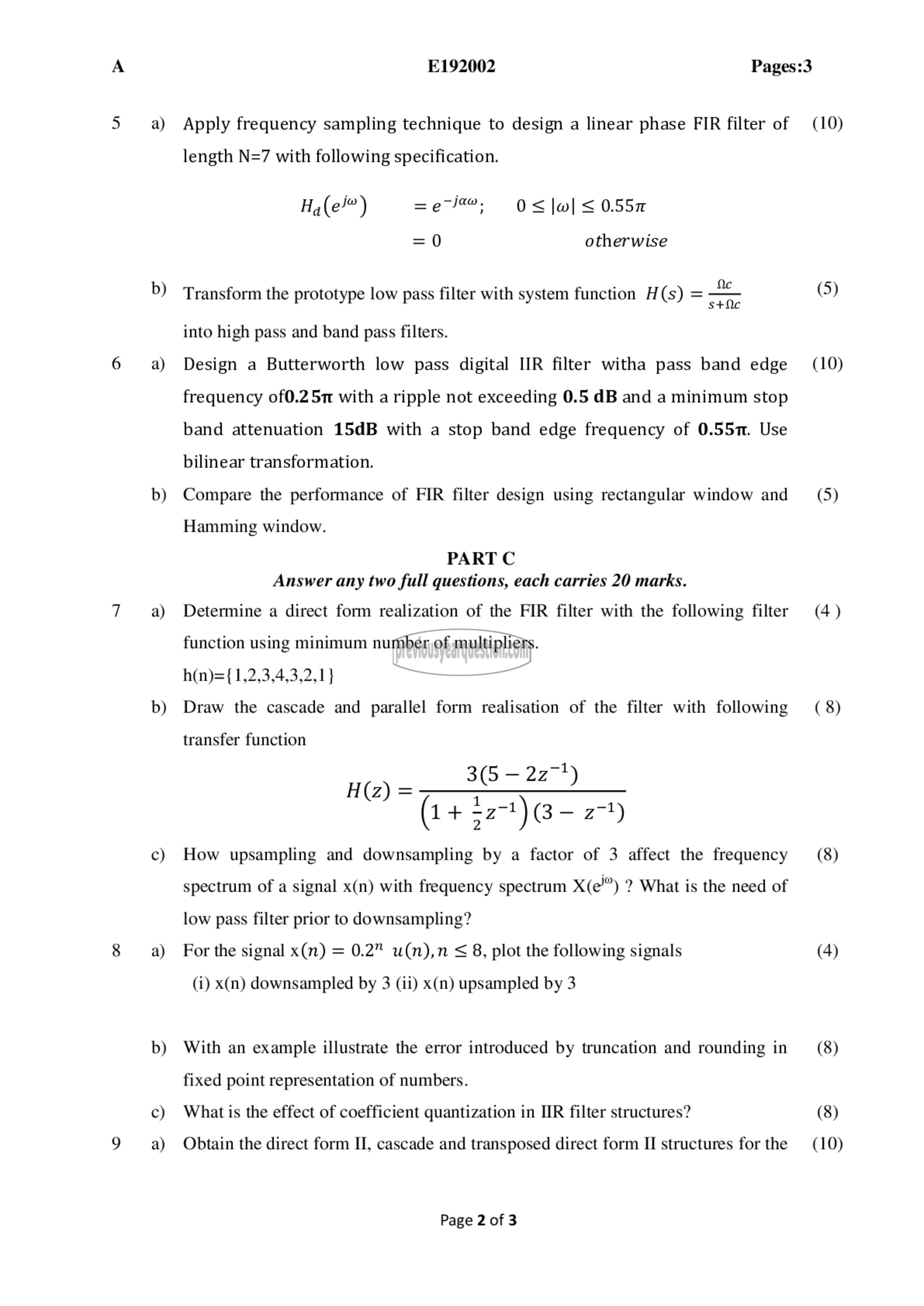
Apply frequency sampling technique to design a linear phase FIR filter of
length N=7 with following specification.
(ല്) =eJ@, 0<|७| > 0.557
=0 otherwise
Transform the prototype low pass filter with system function H(s) = =
into high pass and band pass filters.
Design a Butterworth low pass digital IIR filter witha pass band edge
frequency ೦10.2 जा with a ripple not exceeding 0.5 dB and a minimum stop
band attenuation 15dB with ೩ stop band edge frequency of 0.557. Use
bilinear transformation.
Compare the performance of FIR filter design using rectangular window and
Hamming window.
PART C
Answer any two full questions, each carries 20 marks.
Determine a direct form realization of the FIR filter with the following filter
function using minimum number of multipliers.
h(n)={1,2,3,4,3,2,1}
Draw the cascade and parallel form realisation of the filter with following
transfer function
3(5 - 227)
(1 + 221) (3 ~ 27)
How upsampling and downsampling by a factor of 3 affect the frequency
H(z) =
spectrum of a signal x(n) with frequency spectrum X(e") ? What is the need of
low pass filter prior to downsampling?
For the signal x(n) = 0.2" u(n),n < 8, plot the following signals
(i) x(n) downsampled by 3 (ii) x(n) upsampled by 3
With an example illustrate the error introduced by truncation and rounding in
fixed point representation of numbers.
What is the effect of coefficient quantization in IIR filter structures?
Obtain the direct form II, cascade and transposed direct form II structures for the
Page 2 of 3
(10)
(5)
(10)
(5)
(4)
(8)
(8)
(4)
(8)
(8)
(10)
