APJ ABDUL KALAM TECHNOLOGICAL UNIVERSITY Previous Years Question Paper & Answer
Semester : SEMESTER 3
Subject : Switching Theory and Logic Design
Year : 2018
Term : DECEMBER
Branch : COMPUTER SCIENCE AND ENGINEERING
Scheme : 2015 Full Time
Course Code : CS 203
Page:2
12
13
14
15
16
17
18
19
20
a)
b)
a)
b)
R3925 Pages: 2
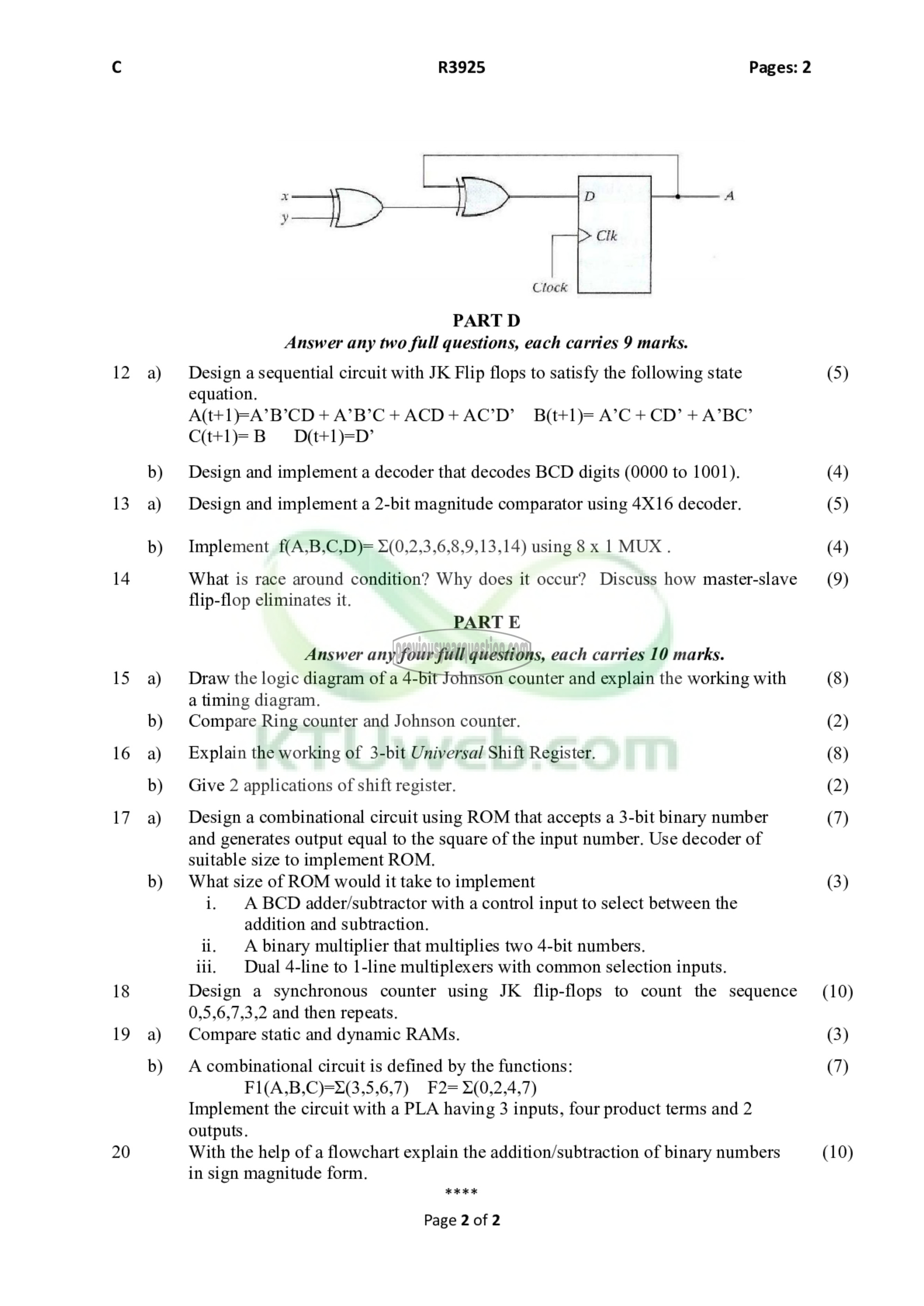
Clock
PART D
Answer any two full questions, each carries 9 marks.
Design a sequential circuit with JK Flip flops to satisfy the following state
equation.
A(t+1=A’B’CD + A’B’C + ^ (7) + ^ (7 86+1)5 A’C + CD’ + A’BC’
((1+1) மரு
Design and implement a decoder that decodes BCD digits (0000 to 1001).
Design and implement a 2-bit magnitude comparator using 4X16 decoder.
Implement f(A,B,C,D)= ೫(0,2,3,6,8,9,13,14) using 8 x 1 MUX.
What is race around condition? Why does it occur? Discuss how master-slave
flip-flop eliminates it.
PART E
Answer any four full questions, each carries 10 marks.
Draw the logic diagram of a 4-bit Johnson counter and explain the working with
a timing diagram.
Compare Ring counter and Johnson counter.
Explain the working of 3-bit Universal Shift Register.
Give 2 applications of shift register.
Design a combinational circuit using ROM that accepts a 3-bit binary number
and generates output equal to the square of the input number. Use decoder of
suitable size to implement ROM.
What size of ROM would it take to implement
i. ABCD adder/subtractor with a control input to select between the
addition and subtraction.
ii. A binary multiplier that multiplies two 4-bit numbers.
iii. | Dual 4-line to 1-line multiplexers with common selection inputs.
Design a synchronous counter using JK flip-flops to count the sequence
0,5,6,7,3,2 and then repeats.
Compare static and dynamic RAMs.
A combinational circuit is defined by the functions:
F1(A,B,C)=2(3,5,6,7) ४25" »(0,2,4,7)
Implement the circuit with a PLA having 3 inputs, four product terms and 2
outputs.
With the help of a flowchart explain the addition/subtraction of binary numbers
in sign magnitude form.
KKK
Page 2 of 2
(5)
(4)
(5)
(4)
(9)
(8)
(2)
(8)
(2)
(7)
(3)
(10)
(3)
(7)
(10)
