APJ ABDUL KALAM TECHNOLOGICAL UNIVERSITY Previous Years Question Paper & Answer
Semester : SEMESTER 6
Subject : Embedded System
Year : 2018
Term : MARCH
Scheme : 2015 Full Time
Course Code : EC 308
Page:90
ICE % an emulator of the mereprecessor of target 0
through a serial link for debugging purposes. ICE emu [ates ಲ 08.೩ ost system connects to the ICE
during development phase using the remaining part of t
lates various versions of a
: microcontroller famil
he target circuit, ,
ff ig an emulator of microprocessor of mi
1೧1 ॥ an emula 007 OF microcontroller of target circuit in a target emulating circuit.
How does an ICE differ from target? The target uses the circuit co
itself. The emulator emulates the target system with extended
during the edit-test-debug cycles, ICE emulates the processor
a card that connects ما the target processor (or circuit) throug
nsisting of the microcontroller or processor
memory and with codes-downloading ability
01 microcontroller. 11 uses another circuit with
h a socket.
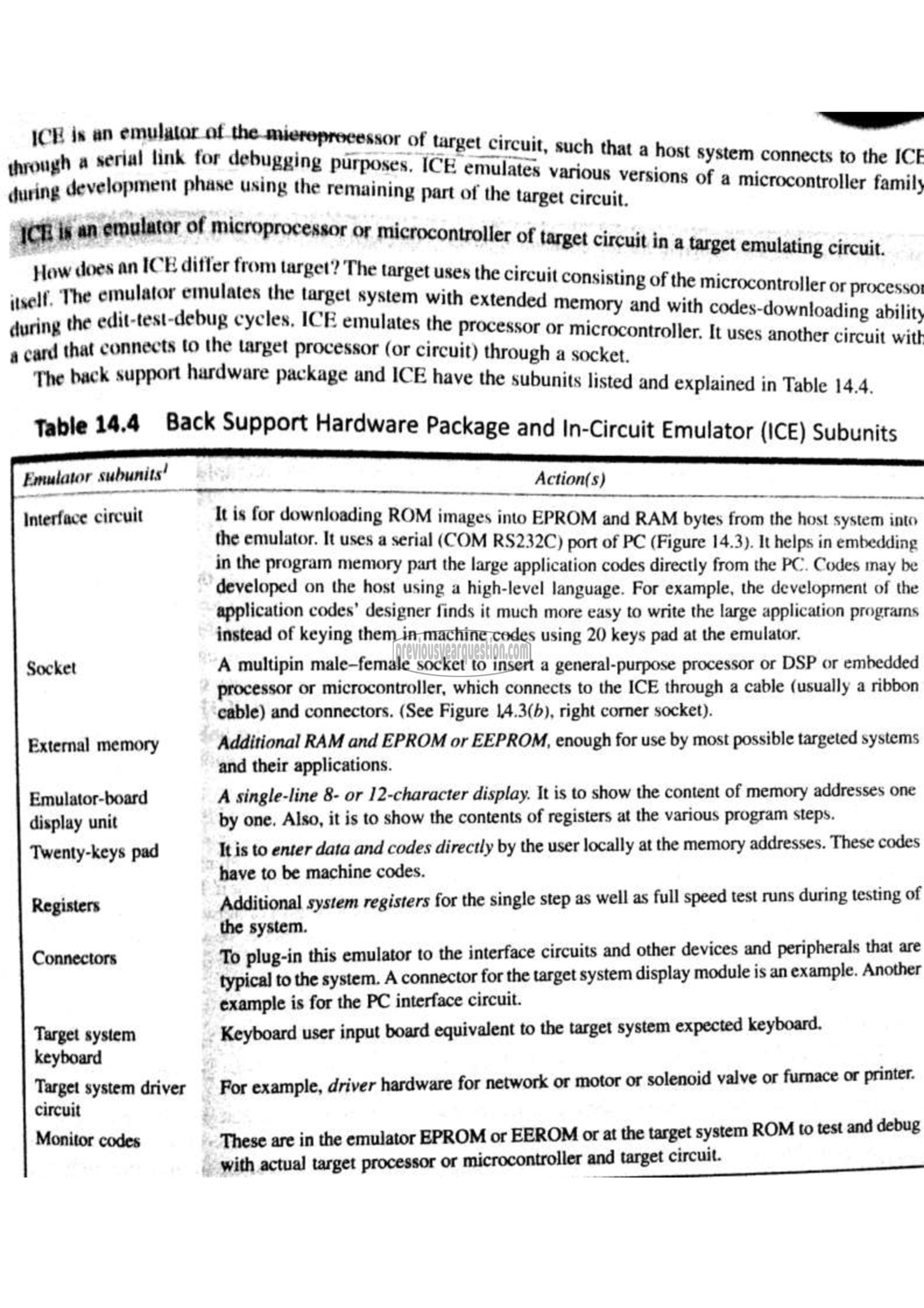
The back support hardware package and ICE have the subunits listed and explained in Table 14.4.
Table 14.4 Back Support Hardware Package and In-Circuit Emulator (ICE) Subunits
subunits! ا
Interface circuit
External memory
Emulator-board
display unit
Twenty-keys pad
Registers
Connectors
Target system
keyboard
Target system driver
circuit
Monitor codes
1
Action(s)
It is for downloading ROM images into EPROM and RAM bytes from the host system into
the emulator. It uses a serial (COM RS232C) port of PC (Figure 14.3). It helps in embedding
in the program memory part the large application codes directly from the PC. Codes may be
developed on the host using a high-level language. For example, the development of the
application codes’ designer finds it much more easy to write the large application programs
instead of keying them in machine codes using 20 keys pad at the emulator.
A multipin male-female socket to insert a general-purpose processor or DSP or embedded
processor or microcontroller, which connects to the ICE through a cable (usually a ribbon
cable) and connectors. (See Figure 14.3(b), right corner socket).
Additional RAM and EPROM or EEPROM, enough for use by most possible targeted systems
and their applications.
A single-line 8- or 12-character display. It is to show the content of memory addresses one
by one. Also, it is to show the contents of registers at the various program steps.
It is to enter data and codes directly by the user locally at the memory addresses. These codes
have to be machine codes.
Additional system registers for the single step as well as full speed test runs during testing of
the system.
To plug-in this emulator to the interface circuits and other devices and peripherals that are
typical to the system. A connector for the target system display module is an example. Another
example is for the PC interface circuit.
Keyboard user input board equivalent to the target system expected keyboard.
For example, driver hardware for network or motor or solenoid valve or furnace or printer.
These are in the emulator EPROM or EEROM or at the target system ROM to test and debug
_ with actual target processor or microcontroller and target circuit.
