APJ ABDUL KALAM TECHNOLOGICAL UNIVERSITY Previous Years Question Paper & Answer
Semester : SEMESTER 4
Subject : Synchronous and Induction Machines
Year : 2019
Term : DECEMBER
Scheme : 2015 Full Time
Course Code : EE 202
Page:2
12
13
14
15
16
17
a)
b)
a)
b)
a)
b)
a)
b)
a)
b)
D192017
PART C
Answer any two full questions, each carries 10 marks.
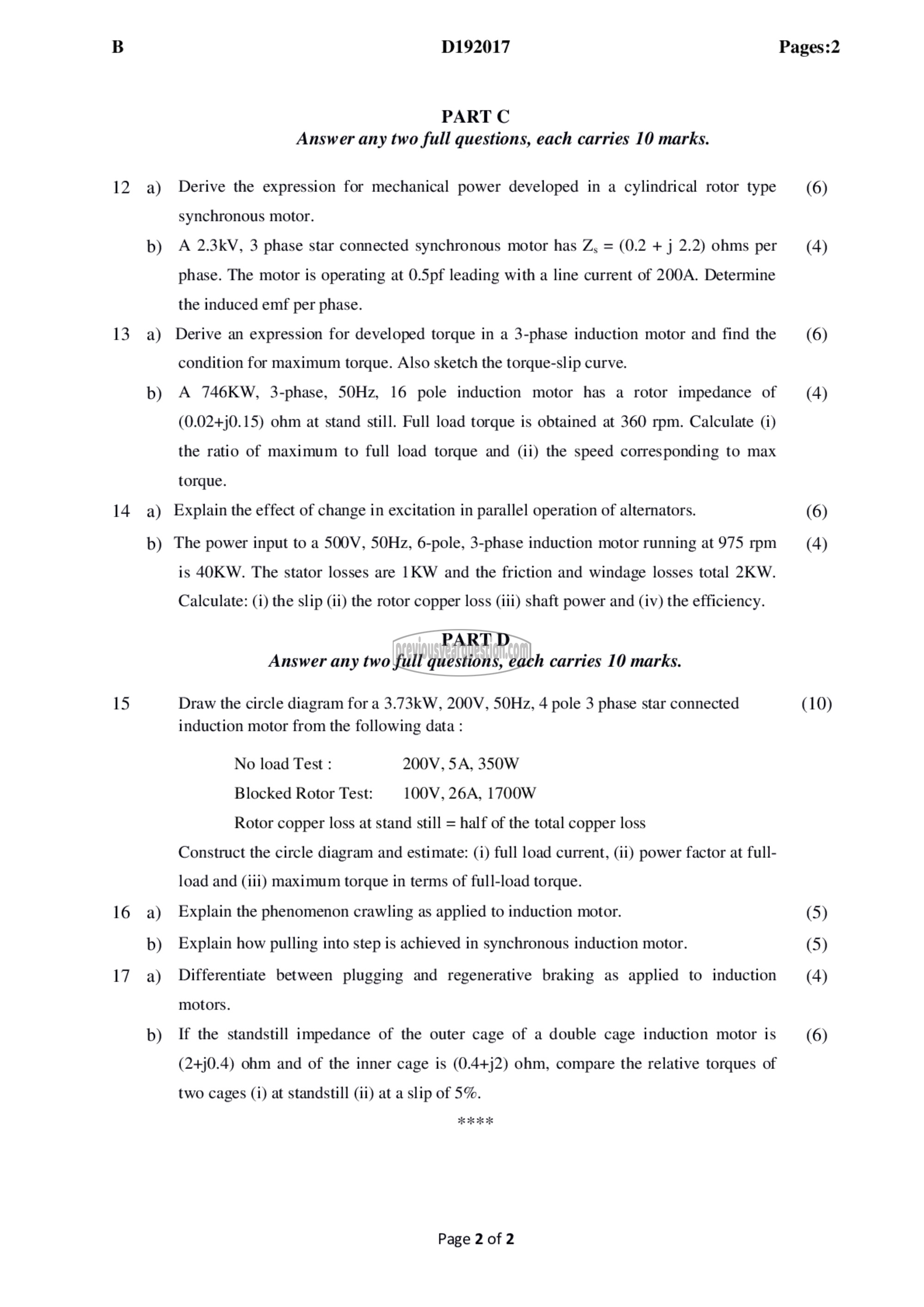
Derive the expression for mechanical power developed in a cylindrical rotor type
synchronous motor.
A 2.3kV, 3 phase star connected synchronous motor has Z, = (0.2 + j 2.2) ohms per
phase. The motor is operating at 0.Spf leading with a line current of 200A. Determine
the induced emf per phase.
Derive an expression for developed torque in a 3-phase induction motor and find the
condition for maximum torque. Also sketch the torque-slip curve.
A 746KW, 3-phase, 50Hz, 16 pole induction motor has a rotor impedance of
(0.02+j0.15) ohm at stand still. Full load torque is obtained at 360 rpm. Calculate (1)
the ratio of maximum to full load torque and (ii) the speed corresponding to max
torque.
Explain the effect of change in excitation in parallel operation of alternators.
The power input to a SOOV, 50112, 6-pole, 3-phase induction motor running at 975 rpm
is 40KW. The stator losses are 1KW and the friction and windage losses total 2K W.
Calculate: (i) the slip (ii) the rotor copper loss (iii) shaft power and (iv) the efficiency.
PART D
Answer any two full questions, each carries 10 marks.
Draw the circle diagram for a 3.73kW, 200۷, 50117, 4 pole 3 phase star connected
induction motor from the following data :
No load Test : 200V, 5A, 350W
Blocked Rotor Test: 100۷, 26A, 1700W
Rotor copper loss at stand still = half of the total copper loss
Construct the circle diagram and estimate: (i) full load current, (ii) power factor at full-
load and (iii) maximum torque in terms of full-load torque.
Explain the phenomenon crawling as applied to induction motor.
Explain how pulling into step is achieved in synchronous induction motor.
Differentiate between plugging and regenerative braking as applied to induction
motors.
If the standstill impedance of the outer cage of a double cage induction motor is
(24j0.4) ohm and of the inner cage is (0.4+j2) ohm, compare the relative torques of
two cages (i) at standstill (ii) at a slip of 5%.
Page 2 of 2
Pages:2
(6)
(4)
(6)
(4)
(6)
(4)
(10)
(5)
(5)
(4)
(6)
