APJ ABDUL KALAM TECHNOLOGICAL UNIVERSITY Previous Years Question Paper & Answer
Semester : SEMESTER 5
Subject : Power ElectronEE305ics
Year : 2018
Term : APRIL
Scheme : 2015 Full Time
Course Code : EE 305
Page:1
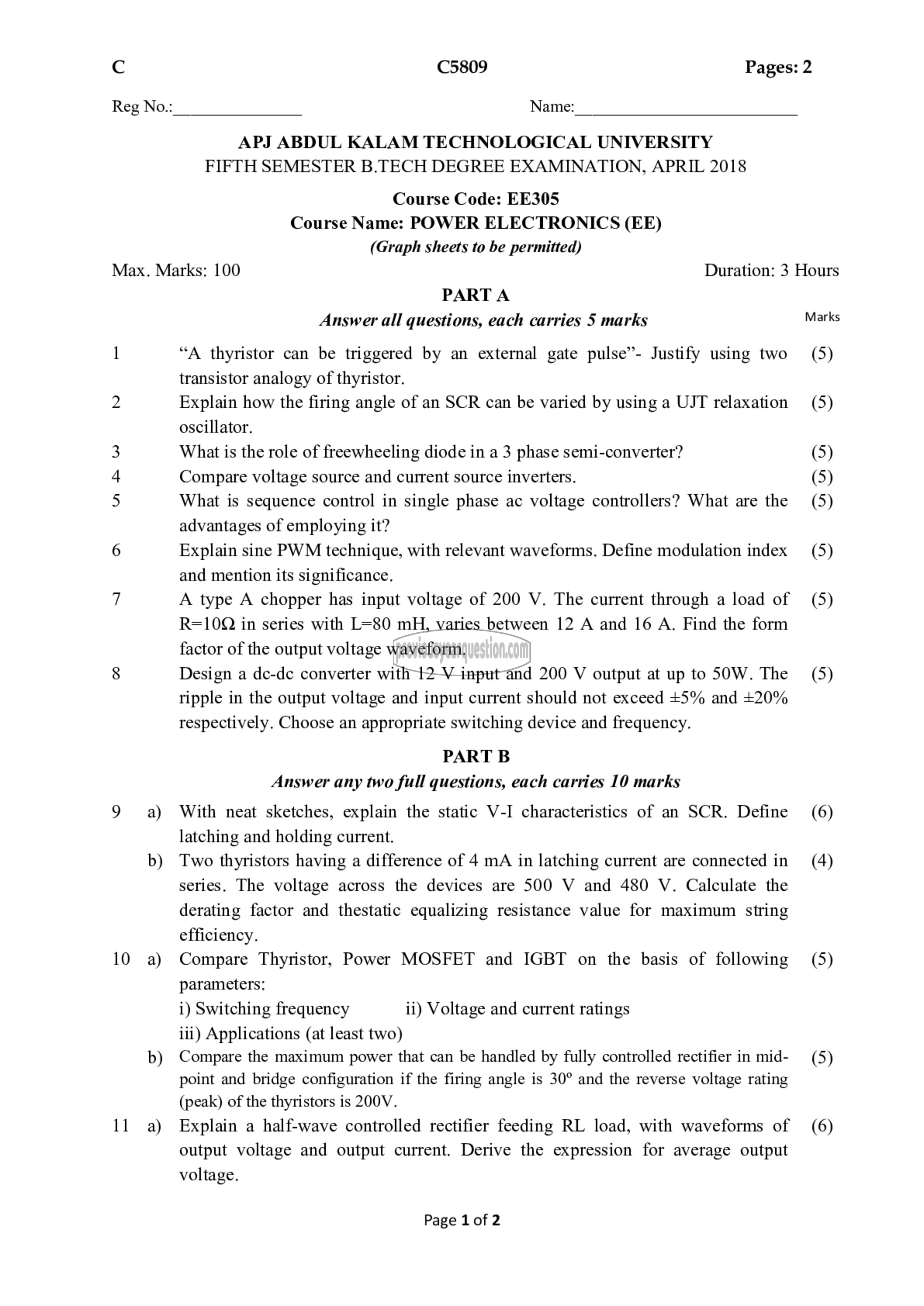
^ (5809 Pages: 2
Reg No.: Name:
APJ ABDUL KALAM TECHNOLOGICAL UNIVERSITY
FIFTH SEMESTER B.TECH DEGREE EXAMINATION, APRIL 2018
Course Code: EE305
Course Name: POWER ELECTRONICS (EE)
(Graph sheets to be permitted)
Max. Marks: 100 Duration: 3 Hours
PART A
Answer all questions, each carries 5 marks Marks
1 “A thyristor can be triggered by an external gate pulse’- Justify using two (5)
transistor analogy of thyristor.
2 Explain how the firing angle of an SCR can be varied by using a UJT relaxation (5)
oscillator.
3 What is the role of freewheeling diode in a 3 phase semi-converter? (5)
4 Compare voltage source and current source inverters. (5)
5 What is sequence control in single phase ac voltage controllers? What are the (5)
advantages of employing it?
6 Explain sine PWM technique, with relevant waveforms. Define modulation index (5)
and mention its significance.
7 A type A chopper has input voltage of 200 V. The current through a load of (5)
R=10Q in series with L=80 mH, varies between 12 A and 16 A. Find the form
factor of the output voltage waveform.
8 Design a 00-60 converter with 12 V input and 200 V output at up to 50W. The (5)
ripple in the output voltage and input current should not exceed +5% and +20%
respectively. Choose an appropriate switching device and frequency.
PART B
Answer any two full questions, each carries 10 marks
9 a) With neat sketches, explain the static V-I characteristics of an SCR. Define (6)
latching and holding current.
b) Two thyristors having a difference of 4 mA in latching current are connected in (4)
series. The voltage across the devices are 500 V and 480 V. Calculate the
derating factor and thestatic equalizing resistance value for maximum string
efficiency.
10 a) Compare Thyristor, Power MOSFET and IGBT on the basis of following (5)
parameters:
i) Switching frequency ii) Voltage and current ratings
iii) Applications (at least two)
b) Compare the maximum power that can be handled by fully controlled rectifier in mid- (5)
point and bridge configuration if the firing angle is 30° and the reverse voltage rating
(peak) of the thyristors is 200V.
11 ஐ Explain a half-wave controlled rectifier feeding RL load, with waveforms of (6)
output voltage and output current. Derive the expression for average output
voltage.
Page 1 of 2
