APJ ABDUL KALAM TECHNOLOGICAL UNIVERSITY Previous Years Question Paper & Answer
Semester : SEMESTER 3
Subject : Electronics Devices & Circuits
Year : 2017
Term : DECEMBER
Branch : COMPUTER SCIENCE AND ENGINEERING
Scheme : 2015 Full Time
Course Code : CS 207
Page:2
10
11
12
13
14
15
16
17
18
19
20
b)
E7252
What is meant by sustained oscillation? What are thecriteria’s for obtaining
sustained oscillations?
An 2512016 multivibrator having 11८5 2KO,R2=20KQ and C)=0.01 pF, ೮0.057,
Determine the period and frequency of oscillation.
PART D
Answer any two full questions, each carries 9 marks.
With the help of circuit diagram explain the working of RC coupled amplifier.
Draw and explain the frequency response of RC coupled amplifier.
With neat diagram explain the working of Hartley oscillator using BJT.
Derive the expression for frequency of oscillation and loop gain of a Hartley
oscillator using BJT.
Explain the effect of negative feedback on amplifiers.
With neat diagram explain the working of monostable multivibrator using BJT
PART E
Answer any four full questions, each carries 10 marks.
With neat diagram explain the working and hysteresis curve of a non inverting
Schmitt trigger using op amp.
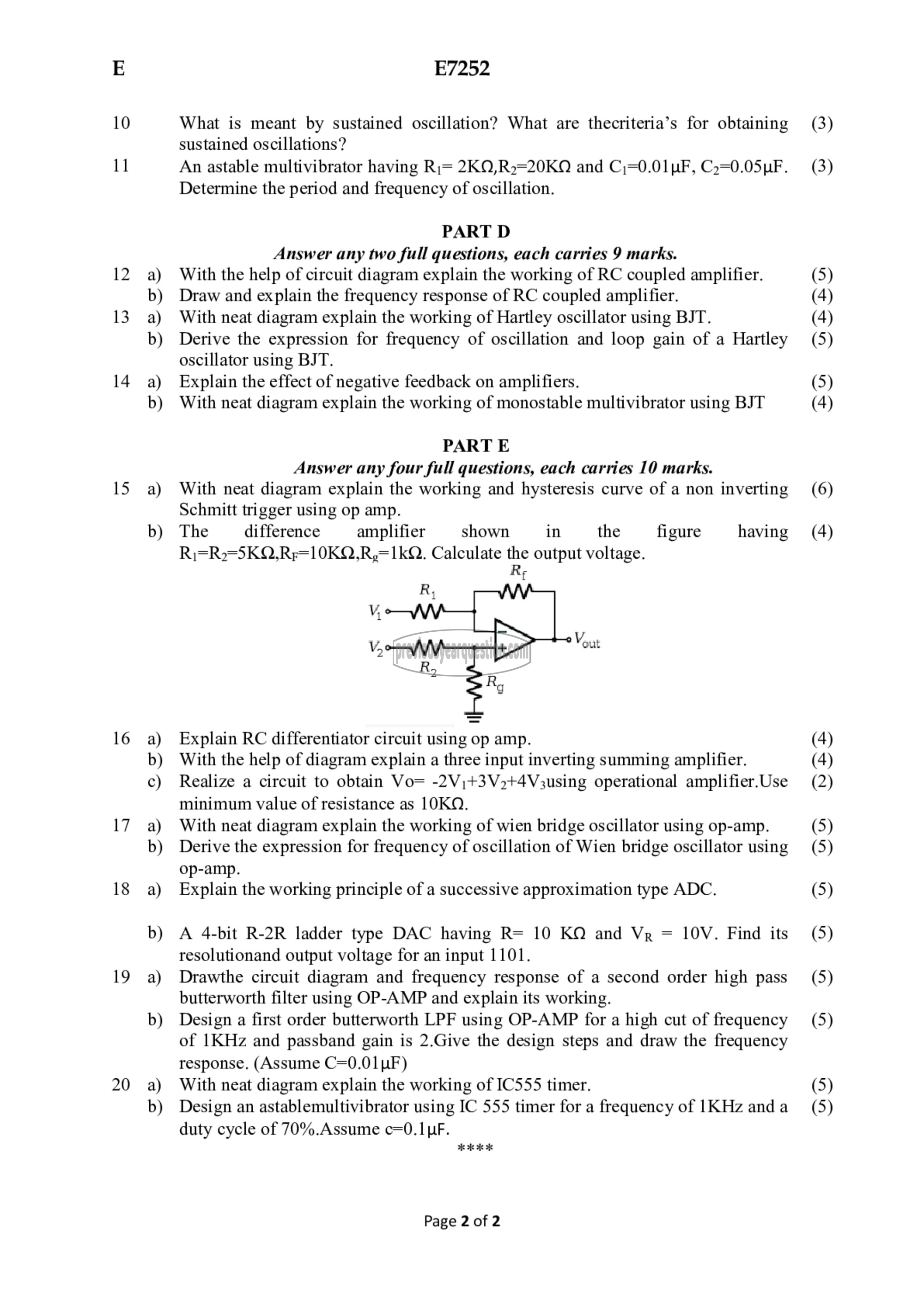
The difference amplifier shown in the figure having
Ri=R2=5SKQO,Rp=10KO,Ro=1kQ. Calculate the output voltage.
Re
Explain RC differentiator circuit using op amp.
With the help of diagram explain a three input inverting summing amplifier.
Realize a circuit to obtain Vo= -2V,+3V2t4V3using operational amplifier.Use
minimum value of resistance as 10KQ.
With neat diagram explain the working of wien bridge oscillator using op-amp.
Derive the expression for frequency of oscillation of Wien bridge oscillator using
op-amp.
Explain the working principle of a successive approximation type ADC.
A 4-bit R-2R ladder type DAC having R= 10 ಓಣ and Vp = 10४. Find its
resolutionand output voltage for an input 1101.
Drawthe circuit diagram and frequency response of a second order high pass
butterworth filter using OP-AMP and explain its working.
Design a first order butterworth LPF using OP-AMP for a high cut of frequency
of 1KHz and passband gain is 2.Give the design steps and draw the frequency
response. (Assume C=0.01 uF)
With neat diagram explain the working of IC555 timer.
Design an astablemultivibrator using IC 555 timer for a frequency of 1 KHz and a
duty cycle of 70%.Assume c=0.1 pF.
HO KK
Page 2 of 2
(3)
(3)
(5)
(4)
(4)
(5)
(5)
(4)
(6)
(4)
(4)
(4)
(2)
(5)
(5)
(5)
(5)
(5)
(5)
(5)
(5)
