APJ ABDUL KALAM TECHNOLOGICAL UNIVERSITY Previous Years Question Paper & Answer
Semester : SEMESTER 6
Subject : Embedded System
Year : 2018
Term : MARCH
Scheme : 2015 Full Time
Course Code : EC 308
Page:89
ட்
In the second mode, buses are Connected to logic analyzer probe pins and the analyser gives the captured
States of all the signals at the clock edge. The triggering point for capturing the states can be defined by the
user. The triggering point can be defined as observation of an illegal op-code or processor at particular startup
address or a certain port byte al output.
For example. the analyzer is set to measure at first, second, third, fourth and so on clock edges, up to 64 or
128 ೧೯ any number (say 229) clock edges from a start address 0x10000. The analyser gives the address and
data bus states in hexadecimal and it gives each control signal state. An advanced version of logic analyzer
can also trace the instruction sequences from the observed address and data bus states at the clock edges from
the given start address. A software engineer can trace illegal instruction or protected address accesses, when
Tunning the codes.
Certain bugs that intermittently arise can also be recorded with a logic analyser by continuous and repeated
runs of the system.
Logic Analyser Inabilities A logic analyser does not help on a program halt due to a bug. 1! does not
show the processor register and memory contents. If the processor uses the caches, bus examination alone
may not help. We cannot modify the memory contents or input parameters during trace and display as we do
im 3 simulator. The effects of these changes are invisible.
With SOC use in embedded systems design, the inner-connections are just not visible to the logic analyzer,
14.3.6 In-Circuit Emulator (ICE)
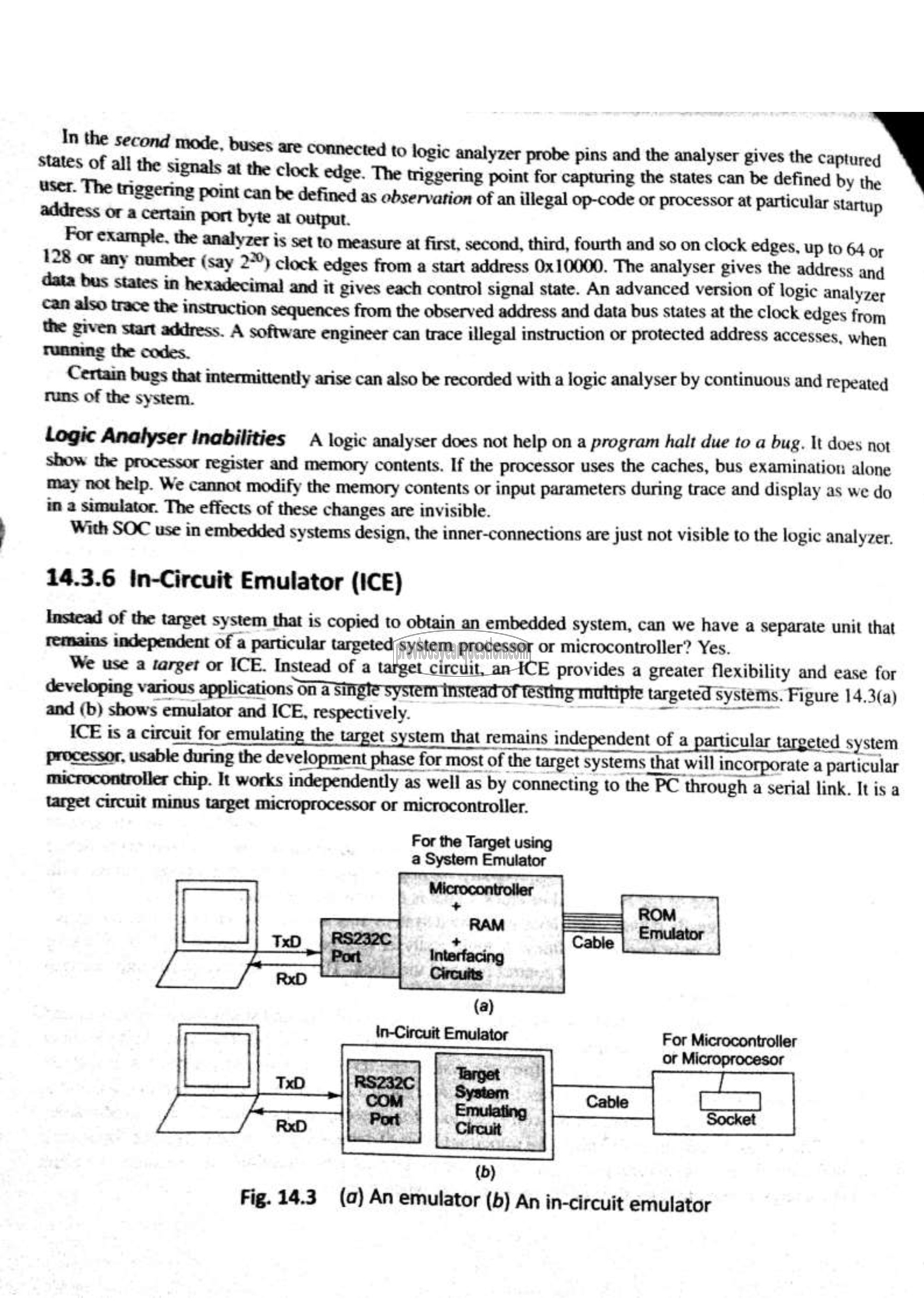
Instead of the target system that is copied to obtain an embedded system, can we have a separate unit that
remains independent of a particular targeted system processor or microcontroller? Yes.
We use a வாச் or ICE. Instead of a target circuit, an ICE provides a greater flexibility and ease for
developing various applications तत उ जहार system instead of testing muttipte as targeted systems. Figure 14.3(a)
and (b) shows emulator and ICE, respectively. ശല
ICE is a circuit for emulating the t target system that remains independen' independent of a particular target ted system
processor, usable during the development phase for most of the target systems that will incorporate a particular
microcontroller chip. It works independently as well as by connecting to the PC through a serial link. It is a
target circuit minus target microprocessor or microcontroller.
For Microcontroller
or Microprocesor
(ರಿ)
Fig. 24.3 (a) An emulator (த) An in-circuit emulator
