APJ ABDUL KALAM TECHNOLOGICAL UNIVERSITY Previous Years Question Paper & Answer
Semester : SEMESTER 6
Subject : Embedded System
Year : 2018
Term : MARCH
Scheme : 2015 Full Time
Course Code : EC 308
Page:87
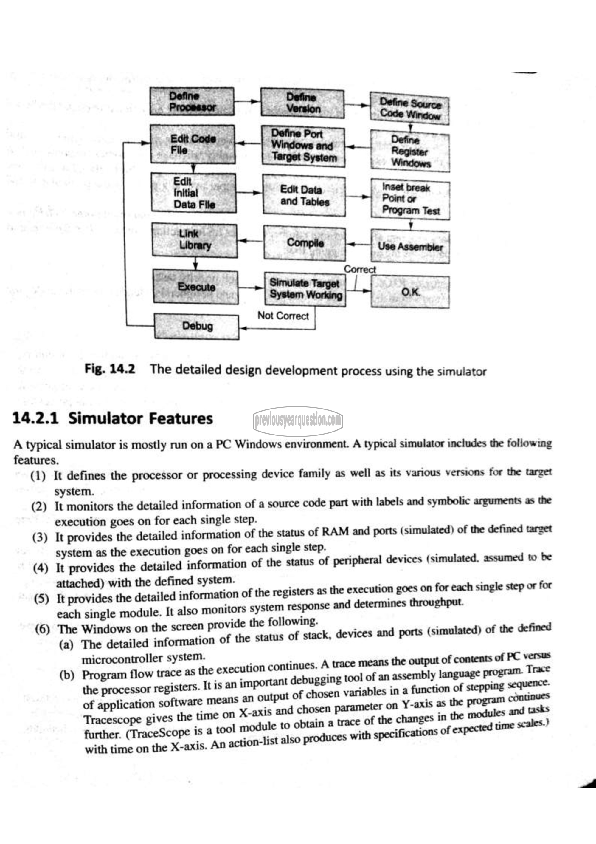
Fig. 14.2 The detailed design development process using the simulator
14.2.1 Simulator Features
A typical simulator is mostly run on a PC Windows environment. A typical simulator includes the following
features.
(1) It defines the processor or processing device family as well as its various versions for the target
system. ಜು
(2) It monitors the detailed information of a source code part with labels and sym arguments as the
execution goes on for each single step. mulated
(3) It provides the detailed information of the status of RAM and ports (simulated) of the defined target
system as the execution goes on for each single step.
(4) It provides the detailed information of the status of peripheral devices (simulated, assumed to be
attached) with the defined system. ۱
(೨ It ಜರ the detailed information of the registers as the execution goes on for each single step or for
each single module. It also monitors system response and determines throughput.
6 i n the screen provide the following.
பூ @ ra جيه information of the status of stack, devices and ports (simulated) of the defined
microcontroller system. ۱ 58
1 _ A trace means the output of contents ಇಷ
w trace as the 70 continues. A னா
யூ سس وا registers. It is an important debugging tool of ആ Am program.
ர் छ lication software means an output of chosen variables in a fun ~= stepping سس :
“ஆணை gives the time on X-axis and chosen (क् 2 em ക 7
i obtain a trace
(TraceScope 15 a tool module to ف ساي ಪ ನತ
च म An action-list also produces with specifications pected scales.
