APJ ABDUL KALAM TECHNOLOGICAL UNIVERSITY Previous Years Question Paper & Answer
Semester : SEMESTER 5
Subject : Power ElectronEE305ics
Year : 2019
Term : DECEMBER
Scheme : 2015 Full Time
Course Code : EE 305
Page:2
12
13
14
15
16
17
b)
a)
b)
a)
b)
E192088 Pages:2
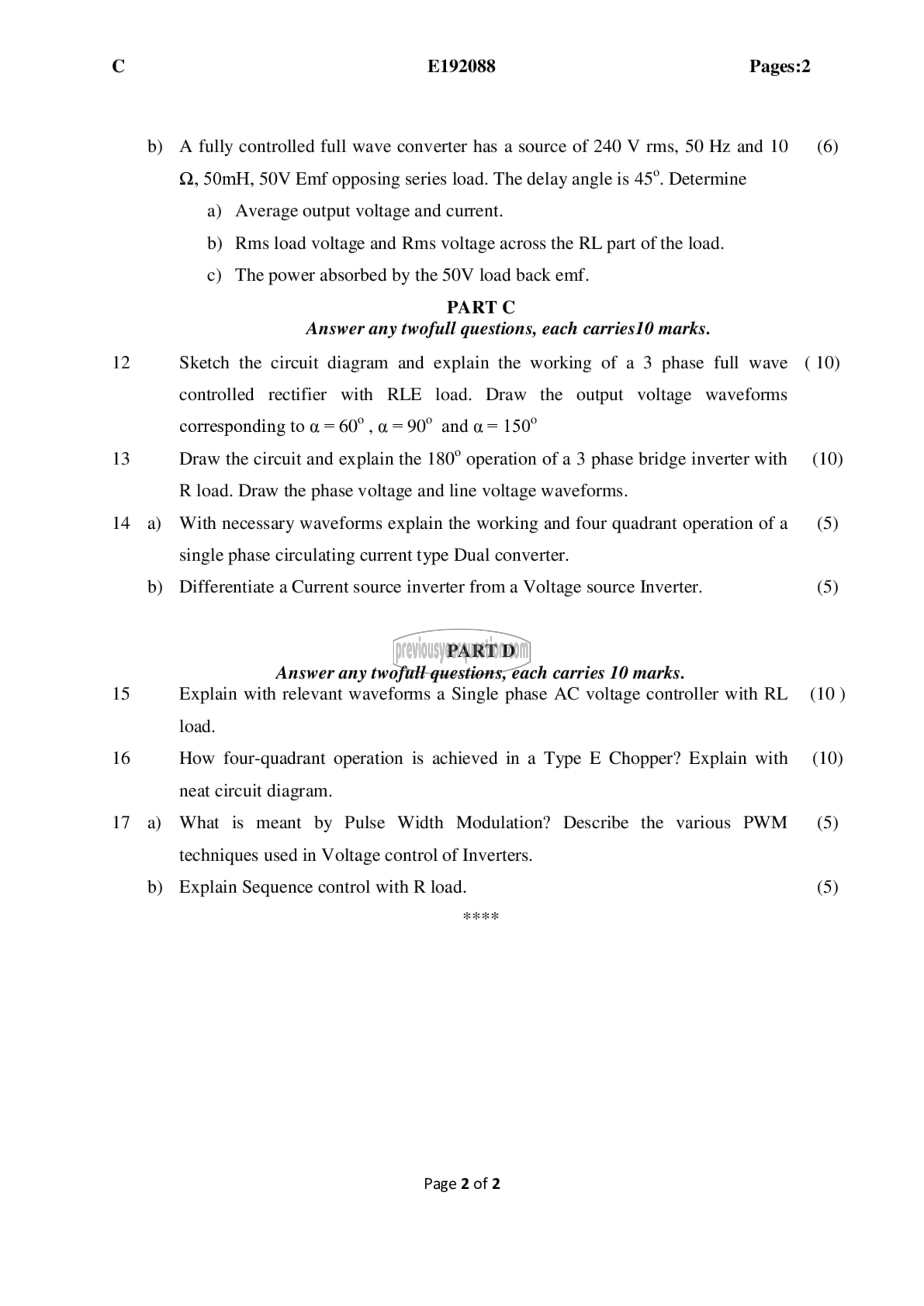
A fully controlled full wave converter has a source of 240 ۷ rms, 50 Hz and 10 (6)
Q, 50mH, 50۷ Emf opposing series load. The delay angle is 45°. Determine
a) Average output voltage and current.
b) Rms load voltage and Rms voltage across the RL part of the load.
c) The power absorbed by the 50V load back emf.
PART ட்
Answer any twofull questions, each carries10 marks.
Sketch the circuit diagram and explain the working of a 3 phase full wave (10)
controlled rectifier with RLE load. Draw the output voltage waveforms
corresponding 10 ० = 60" , و = 90° and a= 150°
Draw the circuit and explain the 180° operation of a 3 phase bridge inverter with (10)
R load. Draw the phase voltage and line voltage waveforms.
With necessary waveforms explain the working and four quadrant operation of ೩ (5)
single phase circulating current type Dual converter.
Differentiate a Current source inverter from a Voltage source Inverter. (5)
PART D
Answer any twofull questions, each carries 10 marks.
Explain with relevant waveforms a Single phase AC voltage controller with RL (10)
load.
How four-quadrant operation is achieved in a Type E Chopper? Explain with (19)
neat circuit diagram.
What is meant by Pulse Width Modulation? Describe the various PWM (5)
techniques used in Voltage control of Inverters.
Explain Sequence control with R load. (5)
Page 2 of 2
