APJ ABDUL KALAM TECHNOLOGICAL UNIVERSITY Previous Years Question Paper & Answer
Semester : SEMESTER 5
Subject : High Voltage Engineering
Year : 2020
Term : SEPTEMBER
Scheme : 2015 Full Time
Course Code : EE 369
Page:2
12
13
14
15
16
17
a)
b)
a)
b)
a)
b)
a)
b)
a)
b)
a)
b)
03000EE369092001
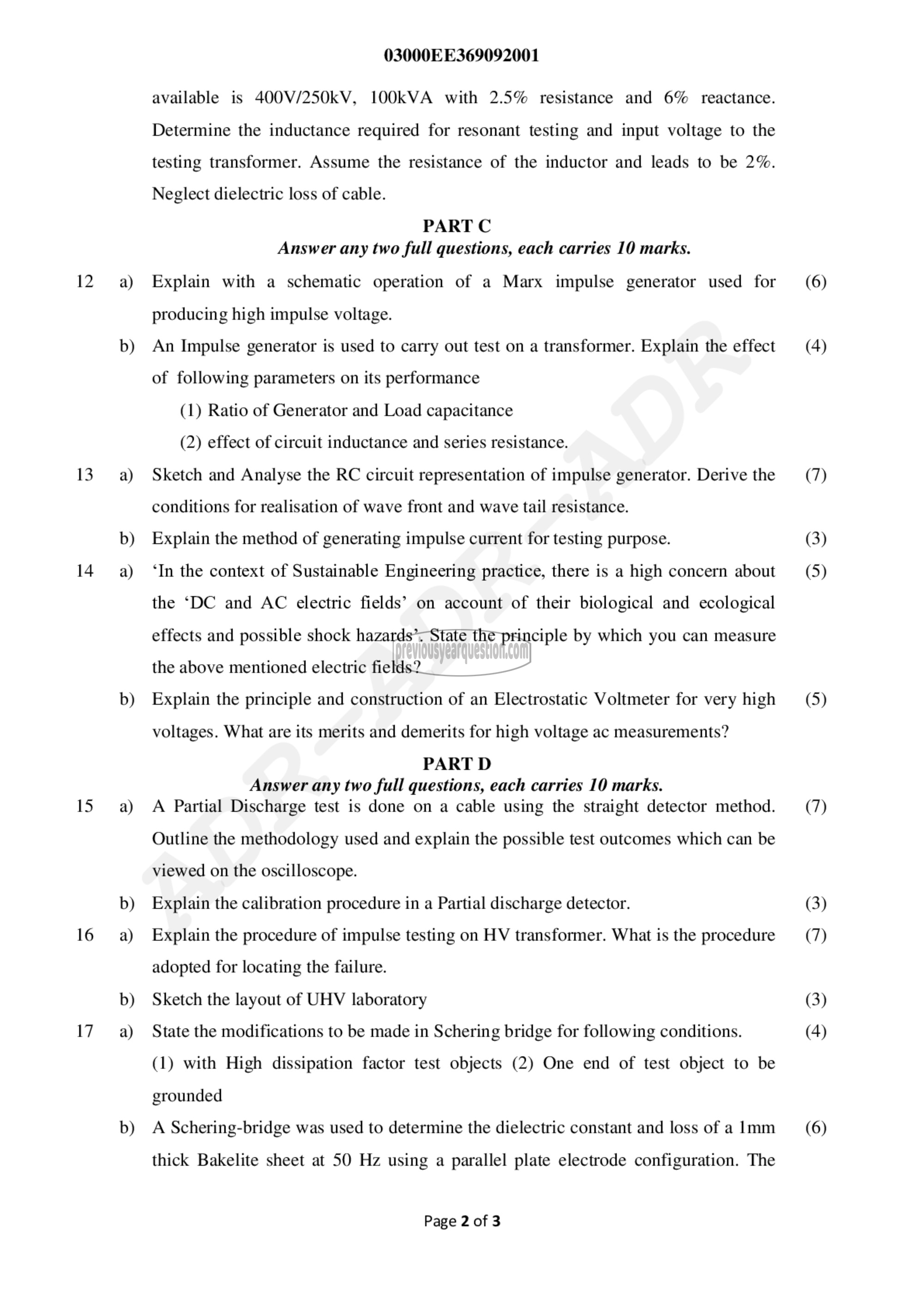
available is 400V/250kV, 10011۷۸ with 2.5% resistance and 6% reactance.
Determine the inductance required for resonant testing and input voltage to the
testing transformer. Assume the resistance of the inductor and leads to be 2%.
Neglect dielectric loss of cable.
PART C
Answer any two full questions, each carries 10 marks.
Explain with a schematic operation of a Marx impulse generator used for
producing high impulse voltage.
An Impulse generator is used to carry out test on a transformer. Explain the effect
of following parameters on its performance
(1) Ratio of Generator and Load capacitance
(2) effect of circuit inductance and series resistance.
Sketch and Analyse the RC circuit representation of impulse generator. Derive the
conditions for realisation of wave front and wave tail resistance.
Explain the method of generating impulse current for testing purpose.
‘In the context of Sustainable Engineering practice, there is a high concern about
the ‘DC and AC electric fields’ on account of their biological and ecological
effects and possible shock hazards’. State the principle by which you can measure
the above mentioned electric fields?
Explain the principle and construction of an Electrostatic Voltmeter for very high
voltages. What are its merits and demerits for high voltage ac measurements?
PART 0
Answer any two full questions, each carries 10 marks.
A Partial Discharge test is done on a cable using the straight detector method.
Outline the methodology used and explain the possible test outcomes which can be
viewed on the oscilloscope.
Explain the calibration procedure in a Partial discharge detector.
Explain the procedure of impulse testing on HV transformer. What is the procedure
adopted for locating the failure.
Sketch the layout of UHV laboratory
State the modifications to be made in Schering bridge for following conditions.
(1) with High dissipation factor test objects (2) One end of test object to be
grounded
A Schering-bridge was used to determine the dielectric constant and loss of a [mm
thick Bakelite sheet at 50 Hz using a parallel plate electrode configuration. The
Page 2 of 3
(6)
(4)
(7)
(3)
(5)
(5)
(7)
(3)
(7)
(3)
(4)
(6)
