APJ ABDUL KALAM TECHNOLOGICAL UNIVERSITY Previous Years Question Paper & Answer
Semester : SEMESTER 3
Subject : Mechanics of Solids
Year : 2019
Term : DECEMBER
Branch : MECHANICAL ENGINEERING
Scheme : 2015 Full Time
Course Code : ME 201
Page:2
a)
b)
a)
b)
a)
b)
C192011 Pages:3
100°C. The Young’s modulus for steel and brass are respectively 200 kN/mm?
and 100 kN/m’. The coefficient of thermal expansion values for steel and brass
are respectively 11.6 x 10% °C and 18.7 x 100 °C,
Derive the torsion formula with assumptions. (8)
Define the term torsional rigidity. (2)
PART تا
Answer any three full questions, each carries 10marks
Distinguish between roller and hinged support. (2)
A simply supported beam has a span of 9 m and carries a uniformly distributed (8)
load of 20 KN/m over the whole span along with two, point loads of 30 KN and
40 KN at 6 m and 7.5 m respectively from the left-hand support. Draw the shear
force and bending moment diagrams indicating values at the point loads.
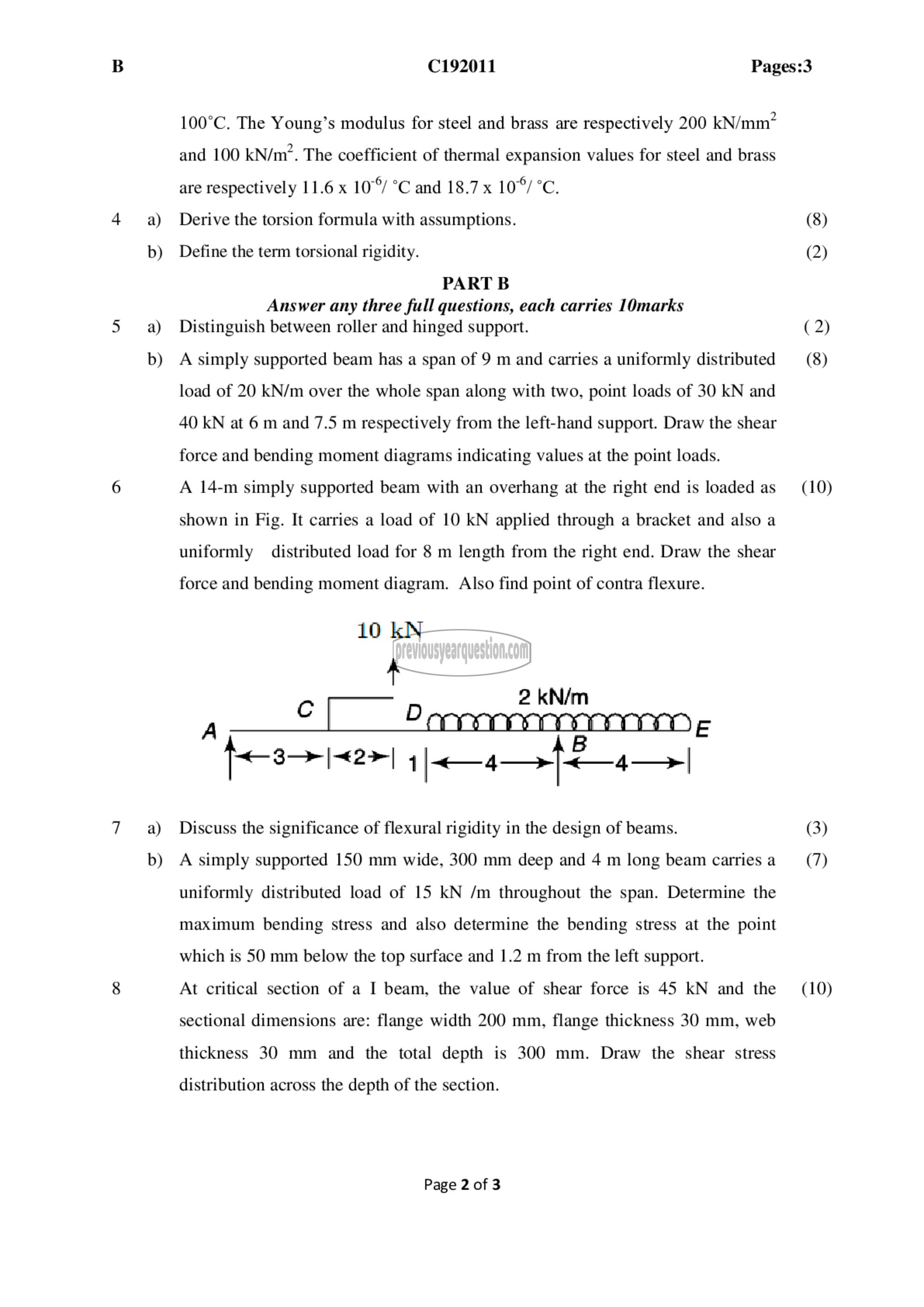
A 14-m simply supported beam with an overhang at the right end is loaded ೩5 (10)
shown in Fig. It carries a load of 10 KN applied through a bracket and also a
uniformly distributed load for 8 m length from the right end. Draw the shear
force and bending moment diagram. Also find point of contra flexure.
10 kN
وہ Dees kN/m
८। 2
A E
॥ 1
3-2 |-<€2> | 1|<—4—>|<—4—>|
Discuss the significance of flexural rigidity in the design of beams. (3)
A simply supported 150 mm wide, 300 mm deep and 4 m long beam carriesa (7)
uniformly distributed load of 15 kN /m throughout the span. Determine the
maximum bending stress and also determine the bending stress at the point
which is 50 mm below the top surface and 1.2 m from the left support.
At critical section of a I beam, the value of shear force is 45 kN and the (10)
sectional dimensions are: flange width 200 mm, flange thickness 30 mm, web
thickness 30 mm and the total depth is 300 mm. Draw the shear stress
distribution across the depth of the section.
Page 2 of 3
