APJ ABDUL KALAM TECHNOLOGICAL UNIVERSITY Previous Years Question Paper & Answer
Semester : SEMESTER 2
Subject : Design of Power Transmission Elements
Year : 2016
Term : MAY
Branch : MACHINE DESIGN
Scheme : 2015 Full Time
Course Code : 01 ME 6112
Page:2
Page 2 of 2
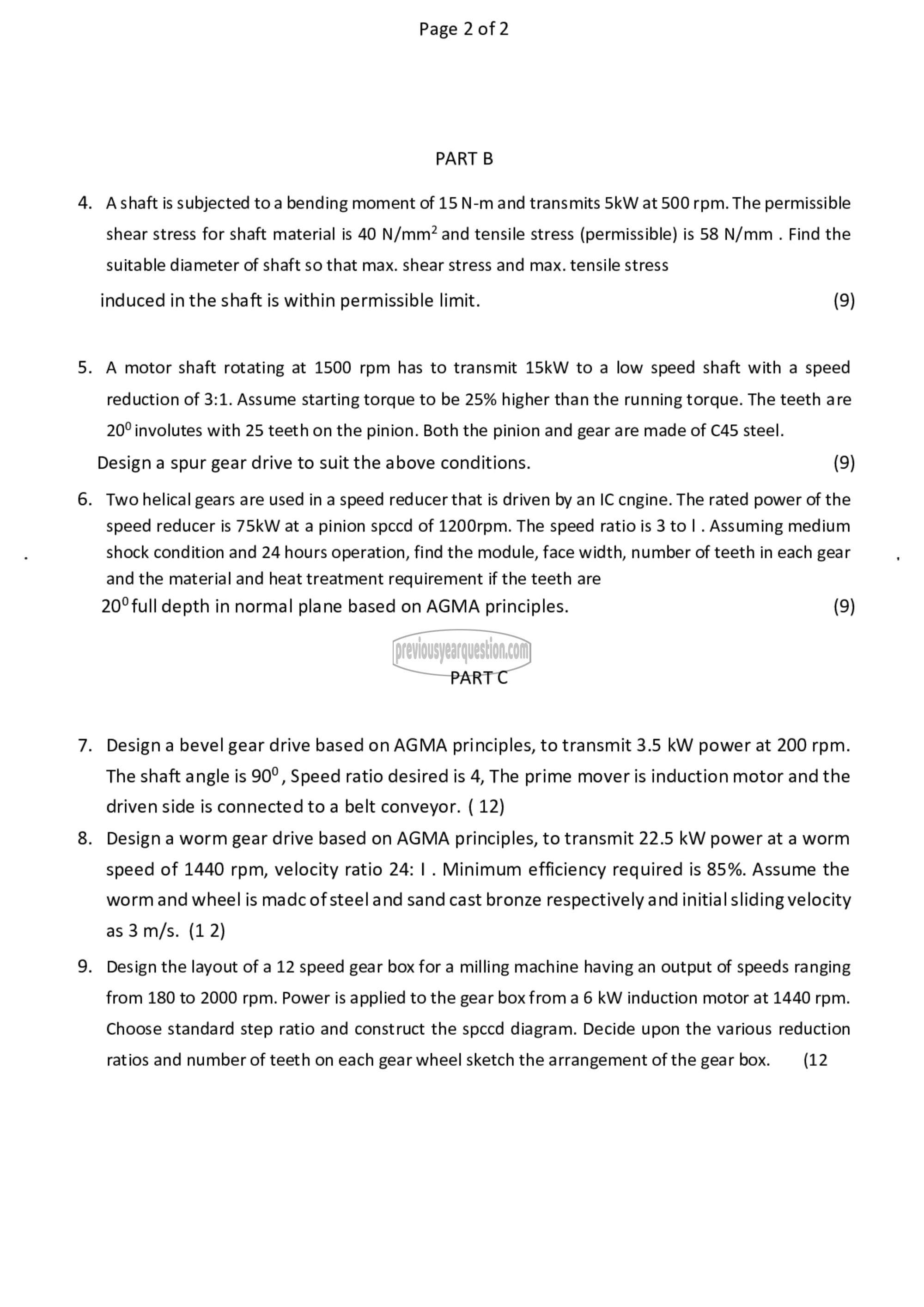
PART B
4. Ashaft is subjected to a bending moment of 15 N-m and transmits 5kW at 500 rpm. The permissible
shear stress for shaft material is 40 N/mm? and tensile stress (permissible) is 58 N/mm . Find the
suitable diameter of shaft so that max. shear stress and max. tensile stress
induced in the shaft is within permissible limit. (9)
5. A motor shaft rotating at 1500 rpm has to transmit 15kW to a low speed shaft with a speed
reduction of 3:1. Assume starting torque to be 25% higher than the running torque. The teeth are
20° involutes with 25 teeth on the pinion. Both the pinion and gear are made of C45 steel.
Design a spur gear drive to suit the above conditions. (9)
6. Two helical gears are used in a speed reducer that is driven by an IC cngine. The rated power of the
speed reducer is 75kW at a pinion spccd of 1200rpm. The speed ratio is 3 to | . Assuming medium
shock condition and 24 hours operation, find the module, face width, number of teeth in each gear
and the material and heat treatment requirement if the teeth are
20° full depth in normal plane based on AGMA principles. (9)
PART C
7. Design a bevel gear drive based on AGMA principles, to transmit 3.5 kW power at 200 rpm.
The shaft angle is 90°, Speed ratio desired is 4, The prime mover is induction motor and the
driven side is connected to a belt conveyor. ( 12)
8. Design a worm gear drive based on AGMA principles, to transmit 22.5 kW power at a worm
speed of 1440 rpm, velocity ratio 24: | . Minimum efficiency required is 85%. Assume the
worm and wheel is madc of steel and sand cast bronze respectively and initial sliding velocity
as 3m/s. (1 2)
9. Design the layout of a 12 speed gear box for a milling machine having an output of speeds ranging
from 180 to 2000 rpm. Power is applied to the gear box from a 6 kW induction motor at 1440 rpm.
Choose standard step ratio and construct the spccd diagram. Decide upon the various reduction
ratios and number of teeth on each gear wheel sketch the arrangement of the gear box. (12
