APJ ABDUL KALAM TECHNOLOGICAL UNIVERSITY Previous Years Question Paper & Answer
Semester : SEMESTER 4
Subject : Measurements and Instrumentation
Year : 2018
Term : MARCH
Scheme : 2015 Full Time
Course Code : EE 208
Page:4
4.
Method of reversal
This test is done by means of several steps. The change in flux density is measured at each step, is the change
from the maximum values +Bmx down to some lower value. But, before the next step is commenced, the iron
specimen is passed through the remainder of the cycle of magnetization back to the flux density +B max. Thus the cyclic
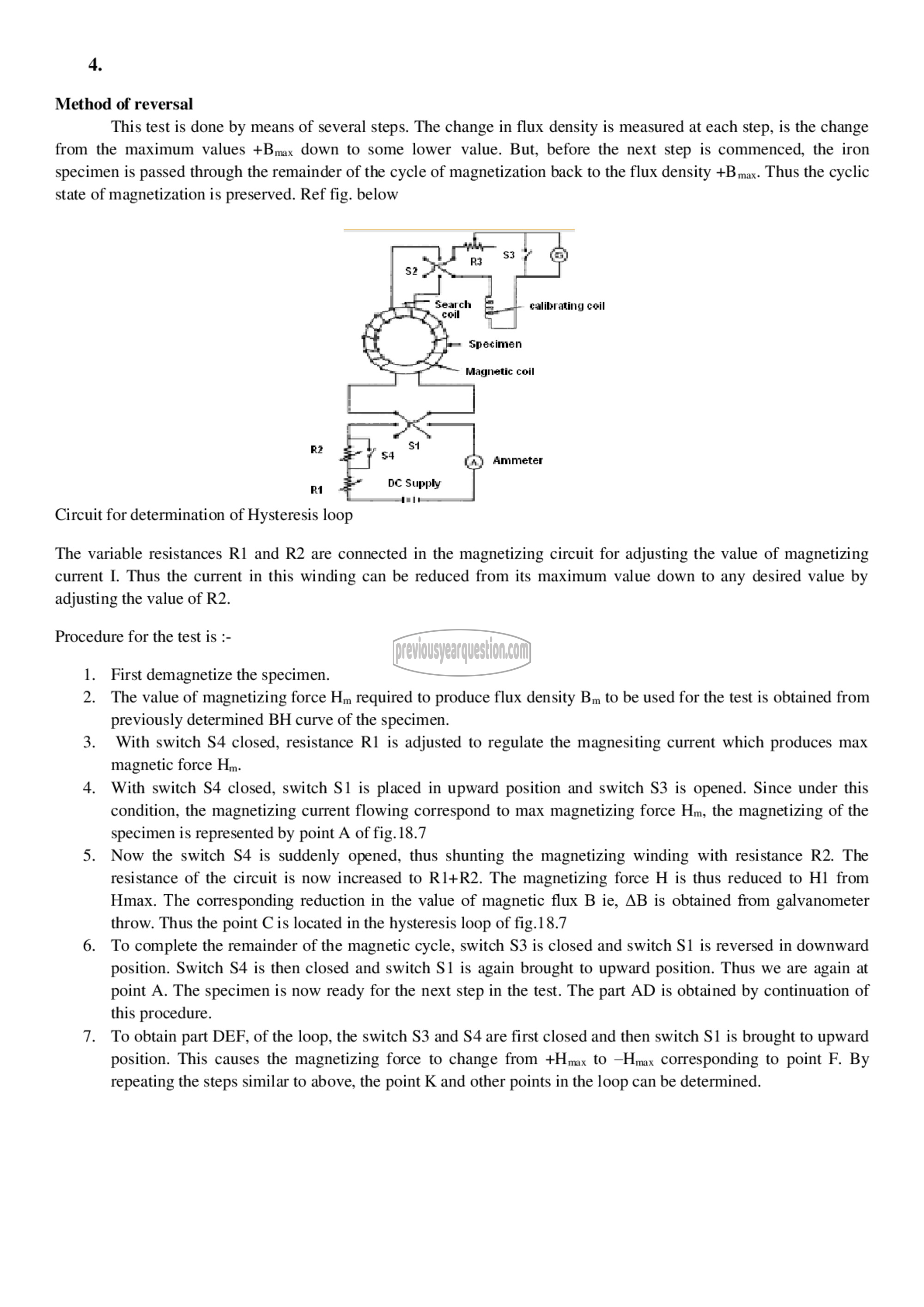
state of magnetization is preserved. Ref fig. below
ட் coil
ce
Magnetic coil
Ammeter
£ 4
Circuit for determination of Hysteresis loop
The variable resistances 81 and R2 are connected in the magnetizing circuit for adjusting the value of magnetizing
current I. Thus the current in this winding can be reduced from its maximum value down to any desired value by
adjusting the value of R2.
Procedure for the test is :-
1. First demagnetize the specimen.
2. The value of magnetizing force Hm required to produce flux density Bm to be used for the test is obtained from
previously determined BH curve of the specimen.
3. With switch 54 closed, resistance R1 is adjusted to regulate the magnesiting current which produces max
magnetic force Hm.
4. With switch S4 closed, switch 51 is placed in upward position and switch 53 is opened. Since under this
condition, the magnetizing current flowing correspond to max magnetizing force Hm, the magnetizing of the
specimen is represented by point A of fig. 18.7
5. Now the switch S4 is suddenly opened, thus shunting the magnetizing winding with resistance R2. The
resistance of the circuit is now increased to 814182. The magnetizing force H is thus reduced to 111 from
Hmax. The corresponding reduction in the value of magnetic flux B ie, AB is obtained from galvanometer
throw. Thus the point C is located in the hysteresis loop of fig.18.7
6. To complete the remainder of the magnetic cycle, switch 53 is closed and switch 51 is reversed in downward
position. Switch 54 is then closed and switch 51 is again brought to upward position. Thus we are again at
point A. The specimen is now ready for the next step in the test. The part AD is obtained by continuation of
this procedure.
7. To obtain part DEF, of the loop, the switch 53 and 54 are first closed and then switch 51 is brought to upward
position. This causes the magnetizing force to change from +Hmx to —Hmax corresponding to point F. By
repeating the steps similar to above, the point K and other points in the loop can be determined.
