APJ ABDUL KALAM TECHNOLOGICAL UNIVERSITY Previous Years Question Paper & Answer
Semester : SEMESTER 4
Subject : Measurements and Instrumentation
Year : 2018
Term : MARCH
Scheme : 2015 Full Time
Course Code : EE 208
Page:22
Power Factor and Loss Angle
i) Power factor (p.f.) : The power factor of the series RC combination is defined as the
cosine of the phase angle of the circuit. Thus,
R
ച്, = ಹಾ گے
ഇ. cos $, 2
For phase angles very close to 90°, the reactance is almost equal to the impedance,
Rx Ry
| p-f = @R, C, |
Fig. 5.14 (6)
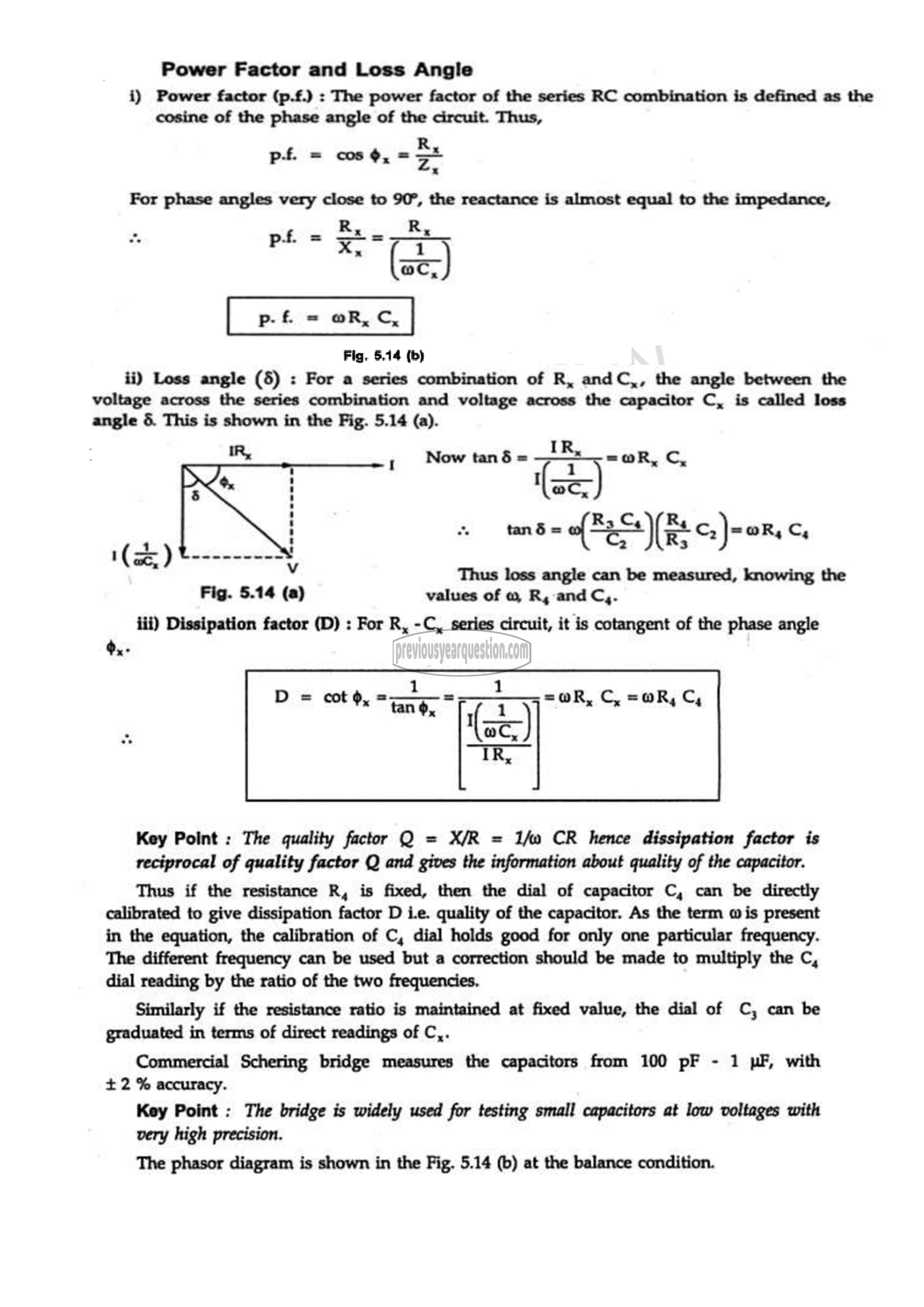
ii) Loss angle (5) : For a series combination of R, andC,, the angle between the
voltage across the series combination and voltage across the capacitor C, is called loss
angle 5. This is shown in the Fig. 5.14 (a).
IR, ‘ மனை عع =@R, டே
ec
tand = എലിന ८५-०६ 3
1 2
aN ⋁
Thus loss angle can be measured, knowing the
Fig. 5.14 (a) values of @ R, and ഠ്യ.
iii) Dissipation factor (D) : For R, -C, series circuit, it is cotangent of the phase angle
ಳ್ಳಿ.
1
"तद्र 0 ات =@R, ഠ്യ
aC,
Key Point : The quality factor Q = X/R = 2/ധ CR hence dissipation factor is
reciprocal of quality factor Q and gives the information about quality of the capacitor.
Thus if the resistance R, is fixed, then the dial of capacitor C, can be directly
calibrated to give dissipation factor D i.e. quality of the capacitor. As the term 015 present
in the equation, the calibration of C, dial holds good for only one particular frequency.
The different frequency can be used but a correction should be made to multiply the C,
dial reading by the ratio of the two frequencies.
Similarly if the resistance ratio is maintained at fixed value, the dial of C, can be
graduated in terms of direct readings of C,.
Commercial Schering bridge measures the capacitors from 100 pF - 1 uF, with
+ 2 % accuracy.
Key Point : The bridge is widely used for testing small capacitors at low voltages with
very high precision.
The phasor diagram is shown in the Fig. 5.14 (0) at the balance condition.
