APJ ABDUL KALAM TECHNOLOGICAL UNIVERSITY Previous Years Question Paper & Answer
Semester : SEMESTER 6
Subject : Embedded System
Year : 2018
Term : MARCH
Scheme : 2015 Full Time
Course Code : EC 308
Page:18
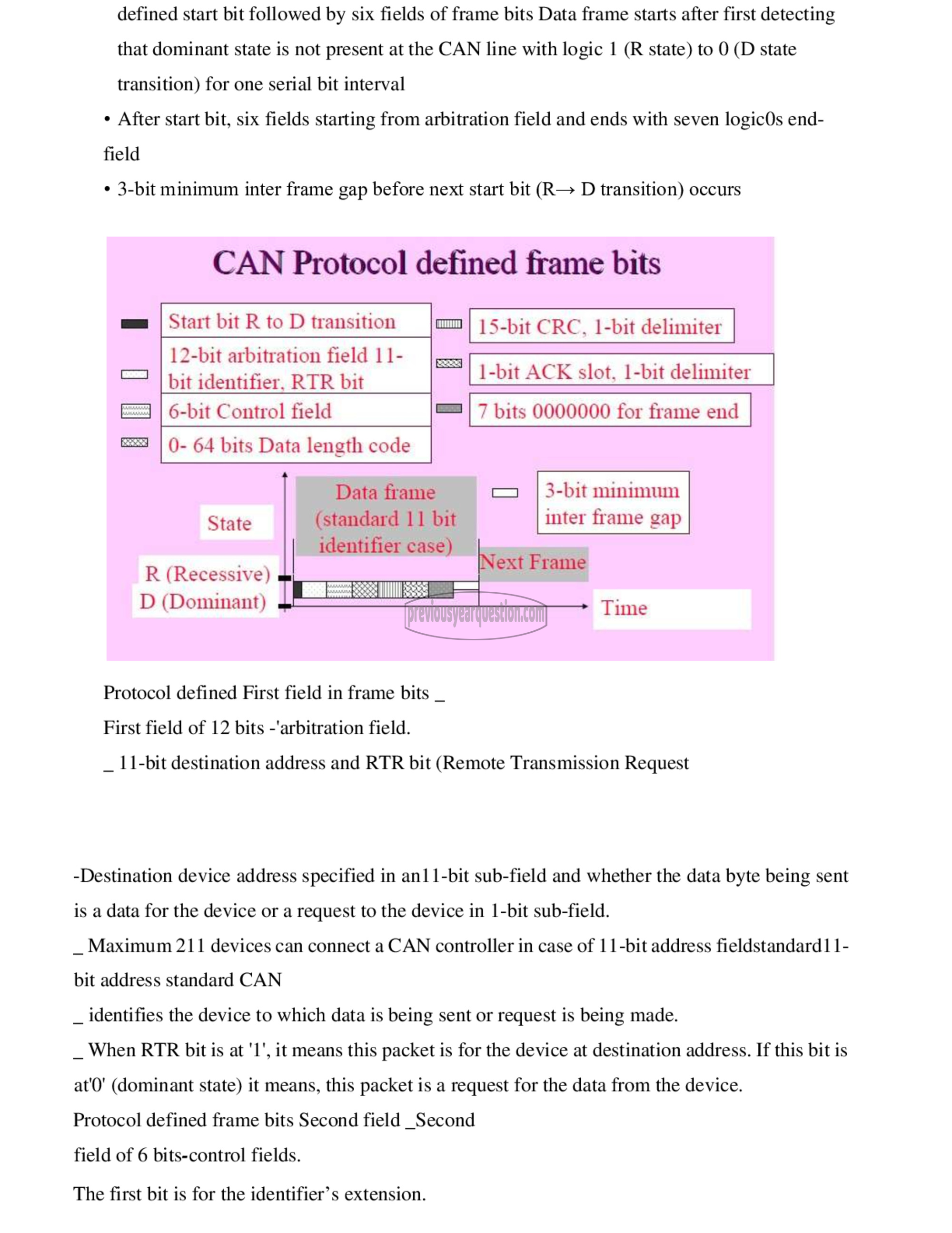
defined start bit followed by six fields of frame bits Data frame starts after first detecting
that dominant state is not present at the CAN line with logic 1 (R state) to 0 (D state
transition) for one serial bit interval
٠ After start bit, six fields starting from arbitration field and ends with seven logicOs end-
field
٠ 3-bit minimum inter frame gap before next start bit (R— D transition) occurs
CAN Protocol defined frame bits
Start bit R to D transition 7 | 15-bit CRC. 1-bit delimiter
12-bit arbitration field 11- 1-bit ACK slot. 1-bit delimiter
bit identifier. RTR bit 1-bit ACK slot, 1-bit delimite1
6-bit Control field ஊ | 7 bits 0000000 for frame end
0- 64 bits Data length code
Data frame ح | 3-bit minimum
State (standard 11 bit inter frame gap
R (Recessive)
D (Dominant)
Protocol defined First field in frame bits _
First field of 12 bits -'arbitration field.
_ 11-bit destination address and RTR bit (Remote Transmission Request
-Destination device address specified in an11-bit sub-field and whether the data byte being sent
is a data for the device or a request to the device in 1-01 sub-field.
ட Maximum 211 devices can connect a CAN controller in case of 11-bit address fieldstandard1 1-
bit address standard CAN
_ identifies the device to which data is being sent or request is being made.
_ When RTR bit is at '1', it means this packet is for the device at destination address. If this bit is
at'0' (dominant state) it means, this packet is a request for the data from the device.
Protocol defined frame bits Second field _Second
field of 6 bits-control fields.
The first bit is for the identifier’s extension.
