APJ ABDUL KALAM TECHNOLOGICAL UNIVERSITY Previous Years Question Paper & Answer
Semester : SEMESTER 3
Subject : Mechanics of Solids
Year : 2018
Term : APRIL
Branch : MECHANICAL ENGINEERING
Scheme : 2015 Full Time
Course Code : ME 201
Page:1
Reg No.:
Max. Marks: 100
1 a)
b)
2 2)
b)
3
4 2)
b)
5
B3803 Pages: 2
Name:
APJ ABDUL KALAM TECHNOLOGICAL UNIVERSITY
THIRD SEMESTER B.TECH DEGREE EXAMINATION, APRIL 2018
Course Code: ME201
Course Name: MECHANICS OF SOLIDS (ME,MP,MA,MT,AU,PE,SF)
PARTA
Answer any three full questions, each carries 10 marks
A metallic bar 30mm diameter is subjected to an axial tensile load of 60kN. The
measured extension on gauge length of 150mm is 0.075mm and change in diameter is
0.00375mm. Calculate Poisson’s ratio, Young’s modulus and modulus of rigidity.
A rod which tapers uniformly from 50mm diameter to 30mm diameter in a length of
1.5m is subjected to an axial force of 150117. Determine the elongation of the rod.
Take E = 200GPa.
State the principle of superposition.
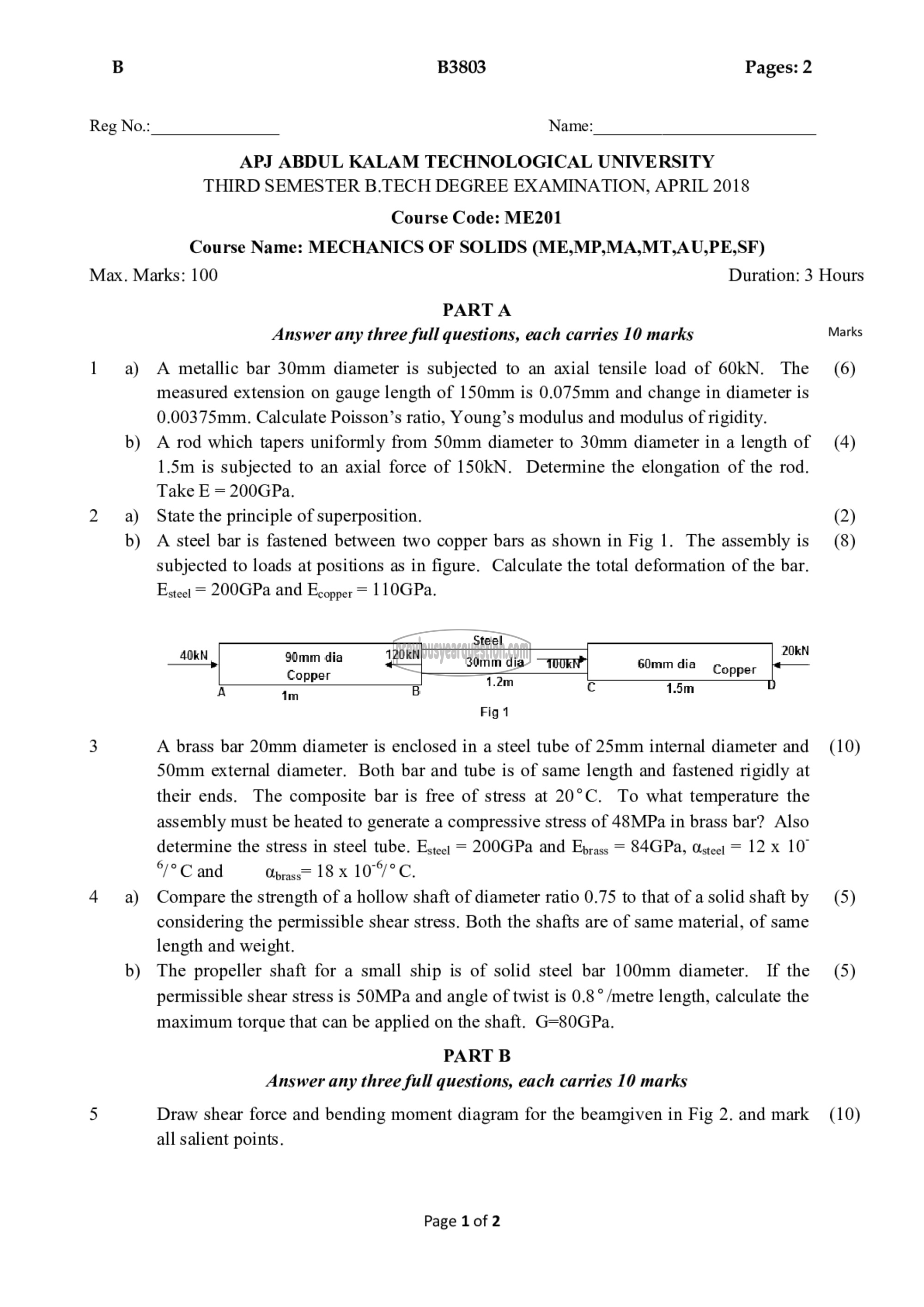
A steel bar is fastened between two copper bars as shown in Fig 1. The assembly is
subjected to loads at positions as in figure. Calculate the total deformation of the bar.
Egteet = 200GPa and Ecopper = 110GPa.
Steel
ணா [र 20kN
പ്ല 30mm dia 0 شالت 30mm dia 11೯7 60mm ا٥ ௫
Copper 1.2m ~~
A in B ⋅ ف 1.5m
Fig 1
A brass bar 20mm diameter is enclosed in a steel tube of 25mm internal diameter and
50mm external diameter. Both bar and tube is of same length and fastened rigidly at
their ends. The composite bar is free of stress at 20°C. To what temperature the
assembly must be heated to generate a compressive stress of 48MPa in brass bar? Also
determine the stress in steel tube. Estee: = 200GPa and Eprass 84078, Osteet = 12 x 10°
6/9೮ and Oprass= 18× 1076,
Compare the strength of a hollow shaft of diameter ratio 0.75 to that of a solid shaft by
considering the permissible shear stress. Both the shafts are of same material, of same
length and weight.
The propeller shaft for a small ship is of solid steel bar 100mm diameter. If the
permissible shear stress is SOMPa and angle of twist is 0.8 ° /metre length, calculate the
maximum torque that can be applied on the shaft. G=80GPa.
PART B
Answer any three full questions, each carries 10 marks
Draw shear force and bending moment diagram for the beamgiven in Fig 2. and mark
all salient points.
Page 1 of 2
Duration: 3 Hours
Marks
(6)
(4)
(2)
(8)
(10)
(5)
(5)
(10)
