APJ ABDUL KALAM TECHNOLOGICAL UNIVERSITY Previous Years Question Paper & Answer
Semester : SEMESTER 5
Subject : Manufacturing Processes
Year : 2018
Term : DECEMBER
Branch : AUTOMOBILE ENGINEERING
Scheme : 2015 Full Time
Course Code : ME 311
Page:1
D R5993 Pages: 2
Reg No.: Name:
APJ ABDUL KALAM TECHNOLOGICAL UNIVERSITY
FIFTH SEMESTER B.TECH DEGREE EXAMINATION, DECEMBER 2018
Course Code: EE311
Course Name: ELECTRICAL DRIVES & CONTROL FOR AUTOMATION
Graph sheet to be provided
Max. Marks: 100 Duration: 3 Hours
PART A
Answer any three full questions, each carries 10 marks. Marks
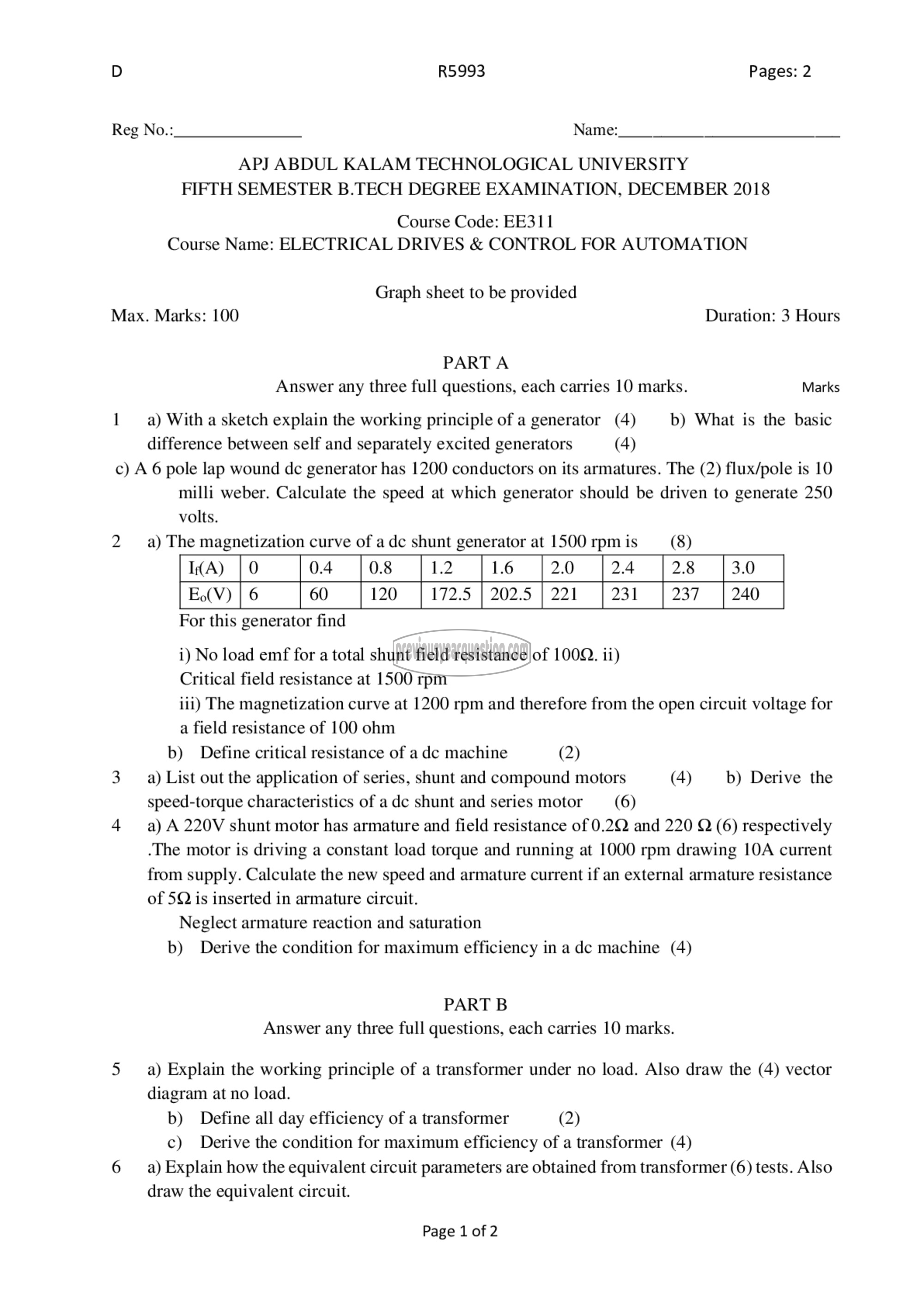
1 ३2) With a sketch explain the working principle of a generator (4) b) What is the basic
difference between self and separately excited generators (4)
c) A 6 pole lap wound de generator has 1200 conductors on its armatures. The (2) flux/pole is 10
milli weber. Calculate the speed at which generator should be driven to generate 250
volts.
2 9) The magnetization curve of a عل shunt generator at 1500 rpm is (8)
14൧) | 0 0.4 0.8 1.2 1.6 | 2.0 2.4 2.8 3.0
E.(V) | 6 60 120 172.5 | 202.5 | 221 231 237 0
For this generator find
i) No load emf for a total shunt field resistance of 100Q. ii)
Critical field resistance at 1500 rpm
iii) The magnetization curve at 1200 rpm and therefore from the open circuit voltage for
a field resistance of 100 ohm
b) Define critical resistance of a dc machine (2)
3 9) List out the application of series, shunt and compound motors (4) b) Derive the
speed-torque characteristics of adc shunt and series motor (6)
4 93) A 22017 shunt motor has armature and field resistance of 0.2Q and 220 Q (6) respectively
.The motor is driving a constant load torque and running at 1000 rpm drawing 10A current
from supply. Calculate the new speed and armature current if an external armature resistance
of 5Q is inserted in armature circuit.
Neglect armature reaction and saturation
b) Derive the condition for maximum efficiency in a dc machine (4)
PART 8
Answer any three full questions, each carries 10 marks.
5 ಖ Explain the working principle of a transformer under no load. Also draw the (4) vector
diagram at no load.
b) Define all day efficiency of a transformer (2)
c) Derive the condition for maximum efficiency of a transformer (4)
6 9) Explain how the equivalent circuit parameters are obtained from transformer (6) tests. Also
draw the equivalent circuit.
Page 1 of 2
