APJ ABDUL KALAM TECHNOLOGICAL UNIVERSITY Previous Years Question Paper & Answer
Semester : SEMESTER 5
Year : 2017
Term : DECEMBER
Branch : MECHANICAL ENGINEERING
Scheme : 2015 Full Time
Course Code : EE 311
Page:2
D7096
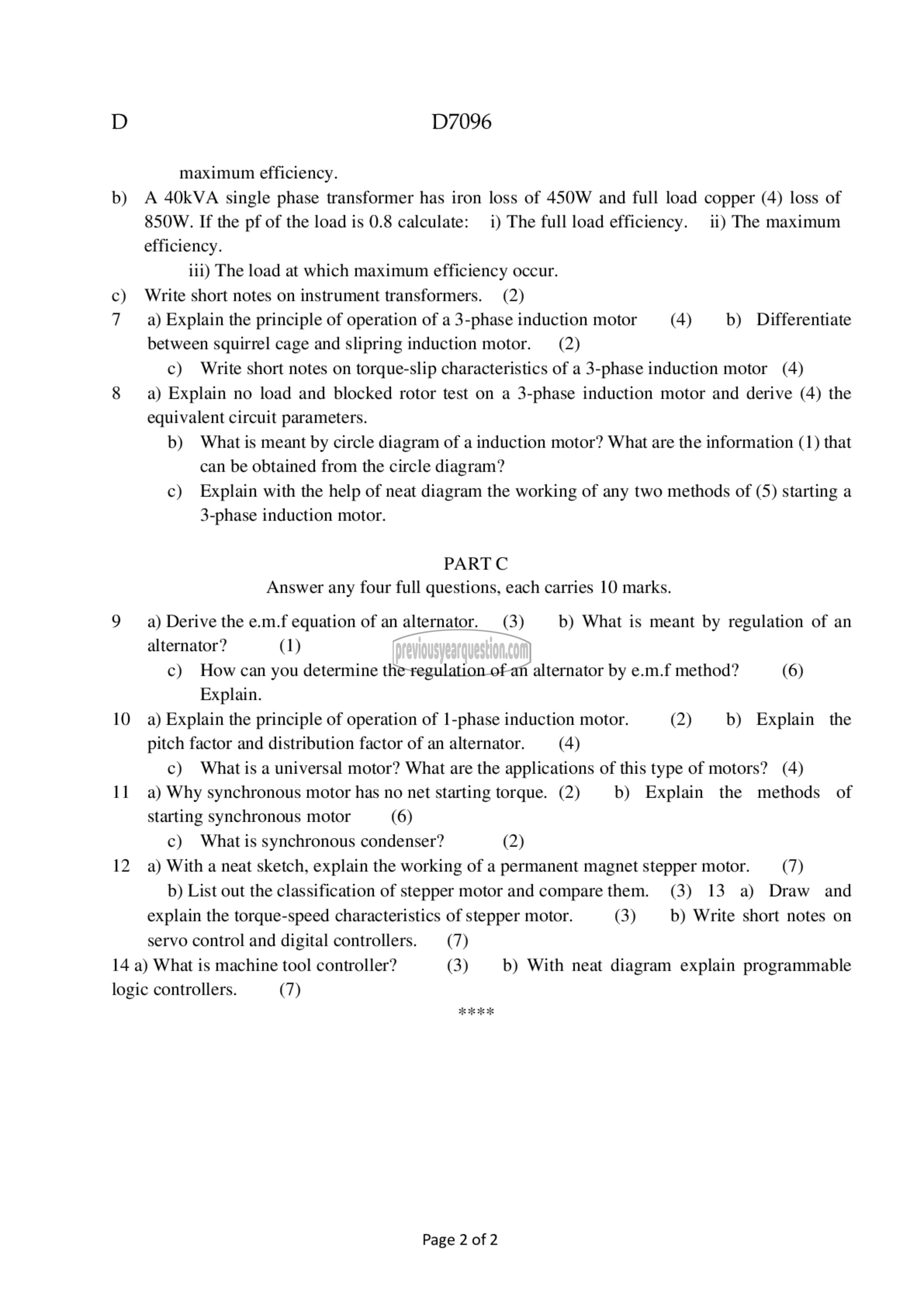
maximum efficiency.
b) A 4011۷۸ single phase transformer has iron loss of 450W and full load copper (4) loss of
850W. If the pf of the load is 0.8 calculate: i) The full load efficiency. ii) The maximum
efficiency.
iii) The load at which maximum efficiency occur.
c) Write short notes on instrument transformers. (2)
7 93) Explain the principle of operation of a 3-phase induction motor (4) b) Differentiate
between squirrel cage and slipring induction motor. (2)
c) Write short notes on torque-slip characteristics of a 3-phase induction motor (4)
8 a) Explain no load and blocked rotor test on a 3-phase induction motor and derive (4) the
equivalent circuit parameters.
b) What is meant by circle diagram of a induction motor? What are the information (1) that
can be obtained from the circle diagram?
c) Explain with the help of neat diagram the working of any two methods of (5) starting a
3-phase induction motor.
PARTC
Answer any four full questions, each carries 10 marks.
9 a) Derive the e.m.f equation of an alternator. (3) b) What is meant by regulation of an
alternator? (1)
c) How can you determine the regulation of an alternator by e.m.f method? (6)
Explain.
10 9) Explain the principle of operation of 1-phase induction motor. (2) 0) Explain the
pitch factor and distribution factor of an alternator. (4)
c) What isa universal motor? What are the applications of this type of motors? (4)
11 a) Why synchronous motor has no net starting torque. (2) b) Explain the methods of
starting synchronous motor (6)
€) What is synchronous condenser? (2)
12 a) With a neat sketch, explain the working of a permanent magnet stepper motor. (7)
b) List out the classification of stepper motor and compare them. (3) 13 a) Draw and
explain the torque-speed characteristics of stepper motor. (3) b) Write short notes on
servo control and digital controllers. (7)
14 a) What is machine tool controller? (3) b) With neat diagram explain programmable
logic controllers. (7)
Page 2 of 2
