APJ ABDUL KALAM TECHNOLOGICAL UNIVERSITY Previous Years Question Paper & Answer
Semester : S1 and S2
Subject : INTRODUCTION TO ELECTRICAL ENGINEERING
Year : 2017
Term : JULY
Branch : MECHANICAL ENGINEERING
Scheme : 2015 Full Time
Course Code : BE 101-03
Page:3
D B1D009S Pages: 4
the m.m.f. required to produce a flux of 0.05 mWb in the airgaps: (ii) the value of the relative
permeability of cast steel at this flux density. The magnetization curve for cast steel is given
by the following (values not present in the table may be approximated as average of the
adjacent values):
(BT) 0.1 | 0.2 | 0.3 10.4
[H(A/m) 170 300 | 380 | 460
(b) State whether the following statements are TRUE or FALSE:
i) In magnetic circuits. flux “flows” like electric current in electric circuits.
ii) Fora steady flux in a magnetic core, there will not be any magnetic 1055.
iii) In reality, the flux density in an air-gap is not the same as that in the magnetic core. *
iv) The slope of B-H curve of a ferromagnetic material such as iron 15 8 constant.
14. (a) Two impedances, 10| ~ 30° and 2060” are connected in parallel. Evaluate the
equivalent impedance. What is the nature (capacitive or inductive) of the equivalent
~~ ^~ 0 impedance? If a current of 101 457 is passing through the parallel combination, calculate the
x 5 voltage across the combination and express it in rectangular form. Evaluate the currents in
each of the impedances. Draw the phasor diagram showing this voltage and all the three
currents. ்
(0) Define peak factor and form-factor. Consider v(t) = 500 cos(100t), a sinusoidal voltage.
Evaluate the rms value and peak factor of the voltage waveform.
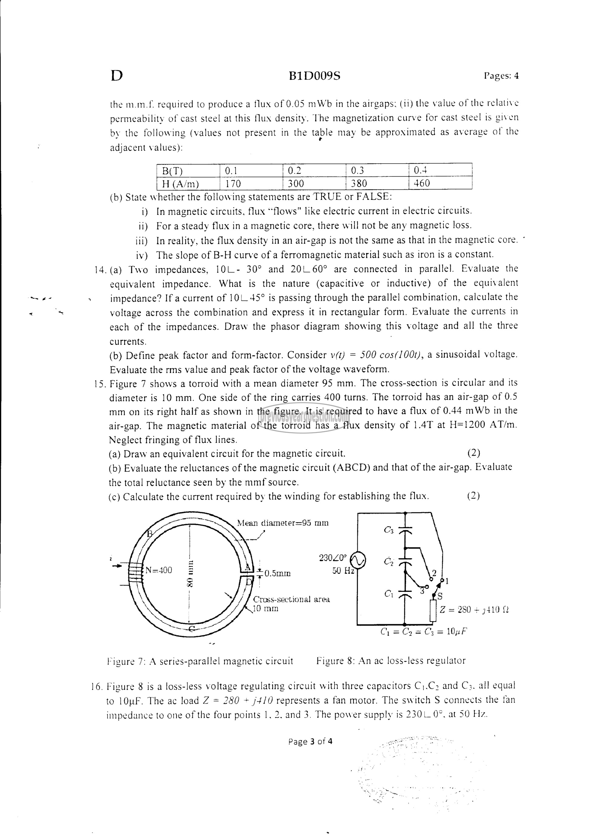
15. Figure 7 shows a torroid with a mean diameter 95 mm. The cross-section is circular and its
diameter is 10 mm. One side of the ring carries 400 turns. The torroid has an air-gap of 0.5
mm on its right half as shown in the figure. It is required to have a flux of 0.44 mWb in the
air-gap. The magnetic material of the torroid has a flux density of 1.4T at H=1200 AT/m.
Neglect fringing of flux lines.
(a) Draw an equivalent circuit for the magnetic circuit. (2)
(b) Evaluate the reluctances of the magnetic circuit (ABCD) and that of the air-gap. Evaluate
the total reluctance seen by the mmf source.
(c) Calculate the current required by the winding for establishing the flux. (2)
+ 0.5mm 60 Hz
Cross-sectional area
10 mm Z = 280 + 1410 ¢
(1 = (2 = Cy = 10017
Figure 7: A series-parallel magnetic circuit Figure 8: An ac loss-less regulator
16. Figure 8 is a loss-less voltage regulating circuit with three capacitors (1.९५ and C3. all equal
to 10൮. The ac load 7 = 280 + j4/0 represents a fan motor. The switch 5 connects the fan
impedance to one of the four points 1, 2. and 3. The power supply is 2301 0°. at 50 Hz.
Page 3 of 4
