APJ ABDUL KALAM TECHNOLOGICAL UNIVERSITY Previous Years Question Paper & Answer
Semester : S1 and S2
Subject : INTRODUCTION TO ELECTRICAL ENGINEERING
Year : 2017
Term : JULY
Branch : MECHANICAL ENGINEERING
Scheme : 2015 Full Time
Course Code : BE 101-03
Page:2
D B1D009S Pages: 4
An R-L series circuit is supplied from an ac voltage source v/t) = 12 cos 41 V. The complex
power delivered by the source is 5 = 3.6+j7.2 VA. Calculate the values of the resistance. र.
and the inductance, L. Evaluate the power factor.
The variation of current against frequency in a series R-L-C circuit is shown in Figure 4.
From the figure, obtain the resonant frequency of the circuit. If at resonance, the total voltage
across the RLC series circuit is 100४. evaluate the resistance in the circuit. What is the power
factor at resonance? Calculate the power dissipated in the RLC circuit at resonance. The
voltage, current etc are expressed in rms values.
Define ‘power factor’ in ac circuits. What is its value for (a) pure resistive circuit. (0) pure
inductive and (c) pure capacitive circuits? ١
A three-phase four-wire system has a balanced load in Y-connection. The phase impedance
of the load is 700 = 10{ 30 ൨. If the line-to-line voltage is 1 = 400 V rms, evaluate the
phase currents in polar form. Evaluate the total active power.
Draw the circuit diagram for measuring power in a three-phase three-wire system using two
wattmeter method, showing clearly the three-phase sources, the two wattmeters and the three-
phase loads connected in star connection. Can this method of power measurement be used for
measuring power with unbalanced three-phase loads?
A three-phase (ABC system assumed) delta connected balanced load is drawing a current of
101 - 30° in the AB arm of the delta. If the A- phase voltage is 23010, draw the phasor
diagram showing all the three phase-currents, three line-currents and three phase- voltages.
Lengths of voltages/currents may be shown at convenient scales. All angles have to be
indicated.
PART B
Answer ANY FOUR full questions. Each full question carries 10 marks.
. (a) State Faraday's laws of electromagnetic induction. Express its mathematical form.
(4)
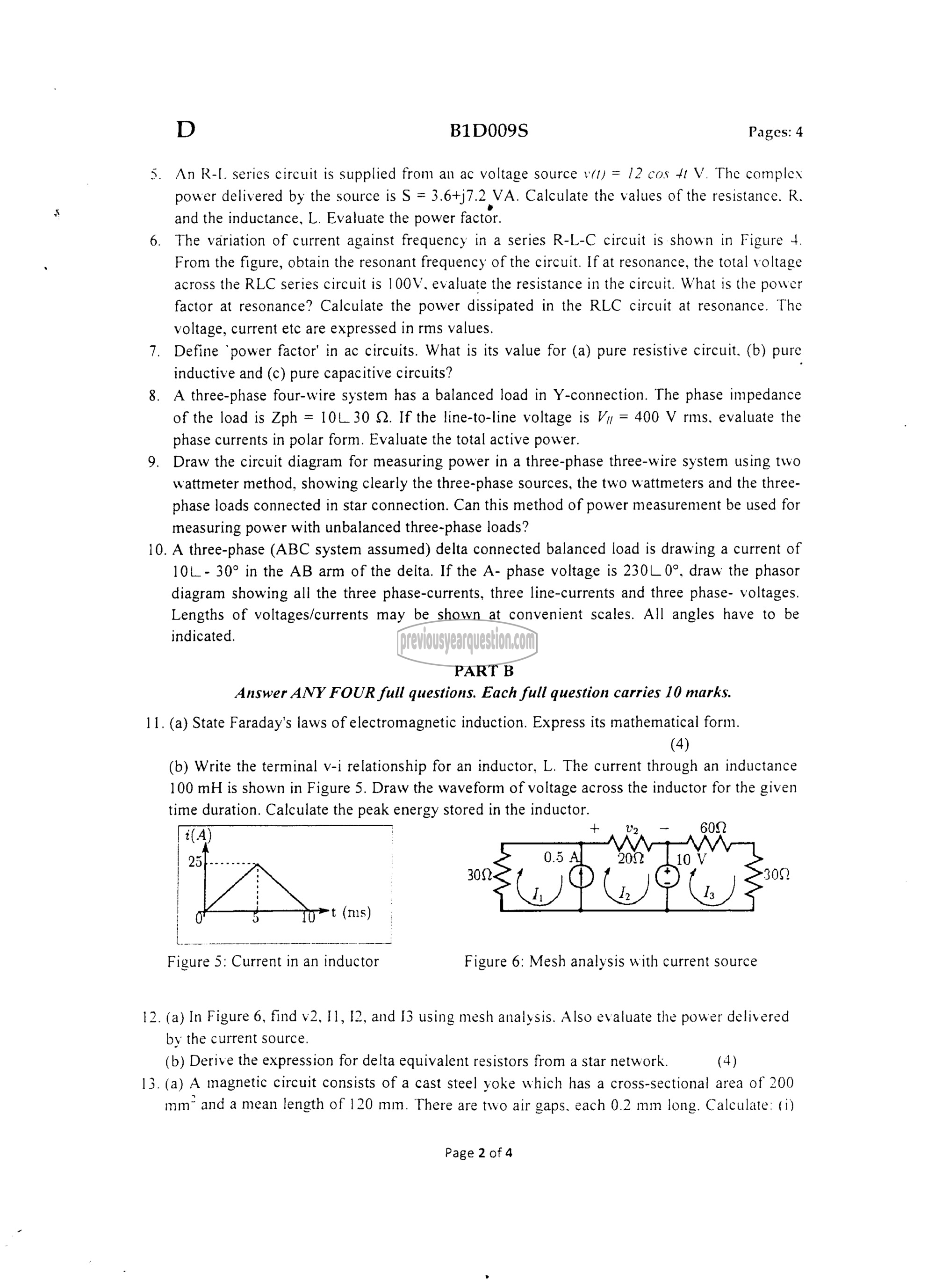
(b) Write the terminal v-i relationship for an inductor, L. The current through an inductance
100 mH is shown in Figure 5. Draw the waveform of voltage across the inductor for the given
time duration. Calculate the peak energy stored in the inductor.
fa) + , 2, ದ , 602
| asf ತ್ನ
| 302 (1) ال 300)
| ⋅ t (ms)
[oo
Figure 5: Current in an inductor Figure 6: Mesh analysis with current source
. (a) In Figure 6, find v2, 11, 12, and 13 using mesh analysis. Also evaluate the power delivered
by the current source.
(b) Derive the expression for delta equivalent resistors from a star network. (4)
. (8) A magnetic circuit consists of a cast steel yoke which has a cross-sectional area of 200
നന് and a mean length of 120 mm. There are two air gaps. each 0.2 mm long. Calculate: (1)
Page 2 4
